Introduction
Understanding how electrical insulating tape works and how to apply it properly separates amateur work from professional results. The difference between a splice that fails in six months and one that holds for decades often comes down to knowing what’s happening at the material level and following proven installation techniques.
Electrical tape isn’t just colored plastic that sticks. It’s an engineered pressure-sensitive adhesive system designed to create a continuous dielectric barrier around conductors, exclude moisture and contaminants, and survive years of temperature cycling and mechanical stress. When applied correctly, it delivers code-compliant insulation for splices rated up to 600 volts in residential and commercial installations, protects automotive wire harnesses from under-hood heat and abrasion, and provides a moisture-tight seal that prevents corrosion and tracking failures.
This guide explains the material science behind electrical insulating tape—how PVC backings and pressure-sensitive adhesives create electrical isolation—and walks through the installation methods that matter: surface preparation, half-lapped wrapping technique, tension control, and when to choose tape versus wire nuts or heat shrink. Whether you’re a DIY homeowner fixing a lamp cord, an electrician working branch circuits, or an automotive technician rebuilding a harness, these principles apply.
![]()
![]()
Material Composition and Structure
Most electrical insulating tapes used by electricians and automotive technicians share a common construction: an elastic polyvinyl chloride (PVC) backing coated on one side with a pressure-sensitive adhesive. This is what’s known in the industry as a single-coated PSA tape – a continuous flexible backing with adhesive applied in a layer thin enough to remain permanently tacky, designed to bond with light hand pressure at room temperature without heat or solvent activation.
The PVC backing provides the dielectric barrier. Plasticized vinyl formulations balance flexibility with mechanical strength, allowing the tape to conform around irregular conductor shapes while resisting puncture and abrasion. Premium grades, such as 3M Temflex 175, specify “elastic PVC backing” that stretches during application and contracts afterward, helping the tape conform tightly and seal out moisture.
The adhesive layer is typically rubber-based – natural or synthetic rubber compounds formulated for aggressive initial tack, good adhesion to insulation jackets and itself, and resistance to moisture, temperature, and the chemicals encountered in electrical environments (alkalis, acids, copper corrosion). Early electrical tapes used sulfur-vulcanized rubber adhesives that promoted corrosion; modern vinyl tapes switched to non-corrosive rubber formulations, eliminating the sulfur while maintaining strength and flexibility.
This two-layer construction – elastic dielectric backing plus pressure-sensitive adhesive – is what gives electrical tape its dual function. The PVC resists electrical breakdown and mechanical damage. The adhesive creates intimate contact, excludes air gaps that could enable tracking or partial discharge, and mechanically bonds each wrap to the previous one, building up a continuous, multilayer insulation barrier.
Industry standards define the expected structure. Pressure Sensitive Tape Council (PSTC) guidelines describe PSA tapes as backings (film, cloth, foil, or paper) coated with adhesives based on rubber, acrylic, or silicone, applied at room temperature with light pressure. Electrical insulating tape falls squarely into this category, and most products on the market follow the vinyl-backing, rubber-adhesive blueprint because it delivers the best balance of electrical, mechanical, and environmental performance at a reasonable cost.
How Electrical Insulation Works

Electrical tape prevents current flow by interposing a high-resistivity, high-dielectric-strength polymer barrier between conductors and everything else – other conductors, grounded surfaces, moisture, and hands. The principle is straightforward: if the electric field across the insulation can’t break down the material and create a conductive path, current stays where it belongs.
Dielectric strength is the key metric. It’s the maximum voltage a material can withstand per unit thickness before electrical breakdown occurs – essentially, how much voltage it takes to punch a hole through the insulator. PVC formulations used in electrical tape typically deliver dielectric strength in the range of tens of kilovolts per millimeter. A product like 3M Temflex 175 lists a minimum dielectric strength of 1000 volts per mil (approximately 40 kV/mm) under ASTM D1000 testing. That means a single layer of 7-mil-thick tape should withstand at least 7,000 volts before breakdown – far above the 600-volt rating for typical residential and commercial branch circuits.
But published dielectric strength is a material property measured under controlled lab conditions. Real-world performance depends on how the tape is applied. Gaps, voids, contamination, and insufficient thickness all create weak points where voltage can concentrate and tracking can begin. Proper wrapping technique – half-lapped layers, controlled tension, clean surfaces – matters as much as the tape’s rated dielectric strength.
The adhesive layer plays a critical role in electrical isolation, even though it’s not the primary dielectric barrier. By creating intimate contact between the PVC backing and the conductor insulation (and between successive wraps), the adhesive eliminates air pockets that could enable corona discharge or surface tracking. Moisture and contaminants collect in gaps; the adhesive seals them out. When the tape stretches slightly during application and then contracts, the elastic recovery presses the adhesive into microscopic textures, maximizing contact area and improving the moisture seal.
UL and CSA testing protocols verify that tapes maintain their insulation properties under stress. UL 510 and CSA C22.2 No. 197 evaluate tapes for dielectric breakdown under dry conditions, at elevated temperature, and after humidity exposure, alongside adhesion, tensile, and aging checks. Vinyl tapes listed to these standards are validated for primary insulation of splices and joints rated up to 600 volts (some products up to 1000 volts), giving electricians and technicians confidence that the tape will perform as claimed when applied per the manufacturer’s instructions.
Electrical insulating tape works by physically separating conductors with a polymer that resists electrical breakdown, backed by an adhesive system that creates a continuous, gap-free seal. The tape’s electrical strength is inherent in the PVC; the seal’s integrity depends on correct installation.
Physical Properties and Performance Ratings
Electrical tape specifications go beyond dielectric strength. Temperature resistance, elongation, adhesive performance, and flame rating all influence whether a tape will survive the conditions it encounters in service. Understanding these properties lets you choose the right tape and predict how it will behave during installation and over time.
Temperature Resistance
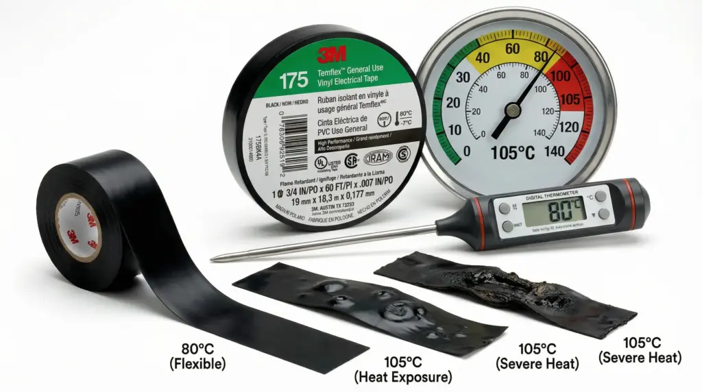
Vinyl electrical tapes are designed for broad ambient temperature ranges. Standard grades like 3M Temflex 175 remain conformable down to around -7°C (19°F) and are rated for continuous use up to 90°C (194°F) under CSA standards, with UL rating typically at 80°C. This window covers most indoor residential and commercial environments. Premium vinyl tapes – Scotch Super 33+ and Super 88 – extend the upper range to 105°C (220°F), making them suitable for applications where conductors run warm under load or where ambient temperatures approach the limits of standard 75°C or 90°C wire insulation.
In automotive harnessing, zone temperature demands are more extreme. Passenger compartment tapes are typically rated to 105°C; engine compartment tapes must withstand continuous exposure at 125°C or higher, resisting heat from exhaust manifolds, turbochargers, and coolant lines without softening, losing adhesion, or degrading. Choose tapes with temperature ratings that match or exceed the environment, and verify those ratings against manufacturer datasheets – not just marketing claims.
Flexibility and Elongation
The elastic PVC backing is what makes electrical tape wrap smoothly around irregular shapes and conform to tight radii without cracking or delaminating. Elongation – the percentage a tape can stretch before breaking – typically runs around 200% for standard vinyl tapes. This stretch contributes to a tight, protective wrap: as you apply tension during wrapping, the tape narrows slightly and conforms to the splice; after application, elastic recovery keeps the wrap snug and helps seal out contaminants.
Elongation also matters during removal or rework. Tapes with good elongation peel off cleanly without tearing into small pieces, speeding service work and reducing frustration. Low-quality tapes with poor elongation crack and fragment, leaving adhesive residue and forcing technicians to scrape and rewrap.
Adhesive Performance
Adhesion is measured in force per unit width—typically ounces per inch or Newtons per centimeter—required to peel the tape from a standard surface (usually stainless steel) at 90 or 180 degrees. A product like Scotch 33 lists adhesion to steel at 24 ounces per inch. Higher values mean stronger hold, which translates to better resistance to flagging (edge lift), better mechanical protection, and longer-lasting seals.
Adhesion to the tape’s own backing is equally important. When you wrap one layer over another, the adhesive must bond to the PVC surface strongly enough to build a unified, multilayer insulation jacket. Poor backing adhesion leads to delamination and loose wraps.
Rubber-based adhesives in electrical tape are formulated to resist moisture, alkalis, acids, and the copper corrosion that plagued early sulfur-cured formulations. They also maintain tack across the service temperature range without becoming brittle in cold or oozing in heat. Some premium tapes use specialized adhesive systems for extreme environments—high-temperature under-hood applications or outdoor UV exposure—where standard rubber adhesives would degrade.
Flammability and Safety
Electrical tapes used in buildings and vehicles must meet flammability standards to limit fire spread. UL 510 includes flame tests; tapes that pass are marked with a UL Listing and temperature class (e.g., “UL 510, 80°C”). In automotive applications, interior materials must comply with FMVSS 302 (U.S. Federal Motor Vehicle Safety Standard 302), which sets maximum burn rate limits in a horizontal flame test.
Choosing a UL-Listed or FMVSS 302-compliant tape isn’t just about meeting code—it’s about ensuring the tape won’t contribute to rapid flame spread if an overcurrent fault, short circuit, or crash ignites nearby materials.
Voltage and Insulation Resistance Ratings
Common vinyl electrical tapes are specified for primary insulation on splices and joints rated up to 600 volts. Some products, particularly those listed to CSA C22.2 No. 197, are validated for use on joints and splices up to 1000 volts when applied in half-lapped layers per the Canadian Electrical Code. The difference between a 600 V and 1000 V rating typically reflects testing protocols and layer count, not fundamentally different materials.
Insulation resistance—measured in megohms after exposure to high humidity—verifies that the tape doesn’t become a leakage path when wet. Quality tapes maintain insulation resistance above 1 million megohms even after conditioning in humid environments, ensuring long-term performance in damp basements, outdoor enclosures, and automotive underbody harnesses.
These ratings and test results aren’t arbitrary numbers—they define the safe operating envelope for the tape. Exceeding the voltage rating, temperature limit, or environmental resistance invites early failure. Staying within spec and following installation guidelines delivers the performance the manufacturer validated and the code requires.
Surface Preparation and Planning
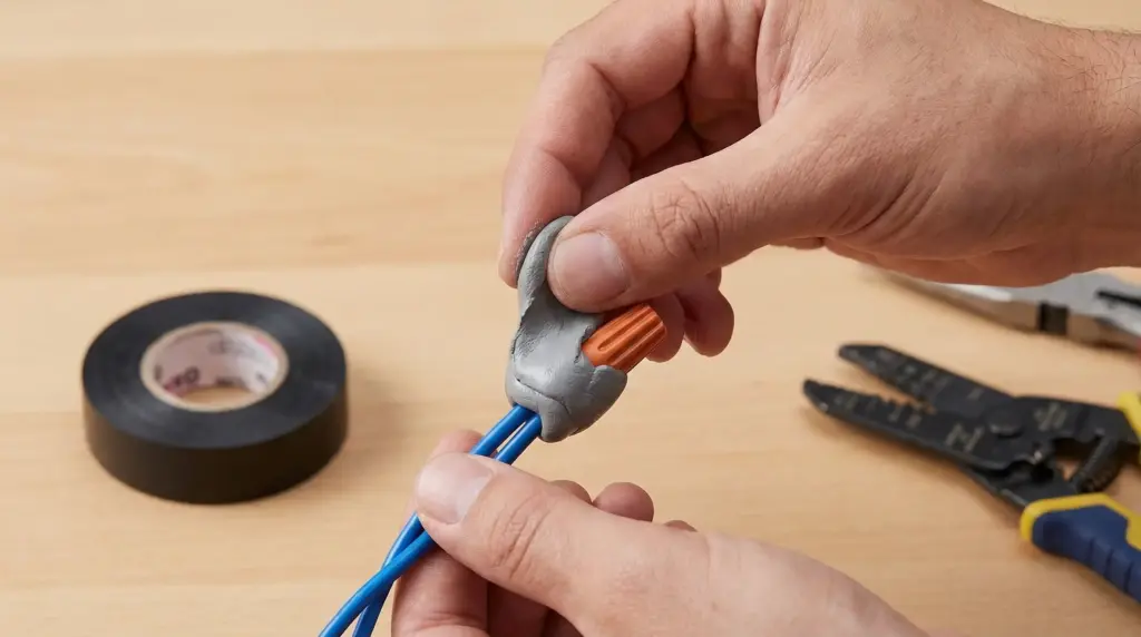
Tape is an insulating layer, not a splicing device. This distinction is fundamental to code-compliant work and safe installations. Before any tape touches a conductor, the electrical joint itself must be made correctly—with listed wire connectors (twist-on, push-in, or crimp), by brazing or welding, or by soldering with a fusible metal alloy. NEC 110.14(B) requires conductors to be spliced with devices identified for the use, then covered with insulation equivalent to the conductors or with an identified insulating device. Tape serves as that insulating cover, not as the splice itself.
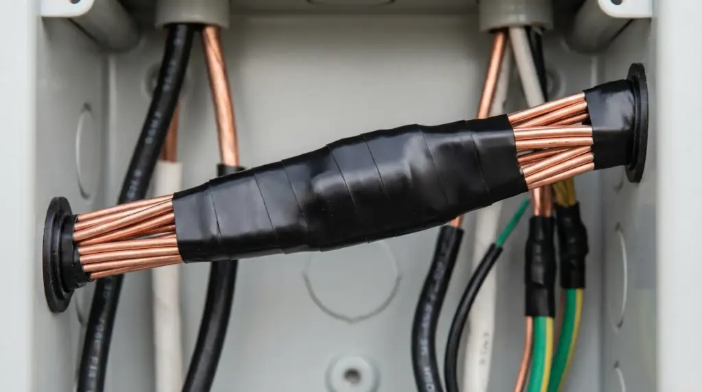
Once the splice is mechanically and electrically sound, preparing it for taping becomes critical. Sharp edges, irregular connector shapes, and voids create stress points that can cut through tape or leave air gaps. Irregular surfaces—pigtail wire ends, hex-shaped wire nuts, crimp barrel edges—need padding. Manufacturer guidelines call for cushioning these areas with electrical putty (such as 3M Scotchfil) or a layer of rubber splicing tape before overwrapping with vinyl. The pad fills voids, rounds off sharp corners, and distributes stress, preventing cut-through and improving the seal.
Surface cleanliness matters less for electrical tape than for structural adhesive tapes, but dust, oils, and loose debris still interfere with adhesion. A quick wipe to remove contaminants improves initial tack and long-term hold. In automotive harnessing, where tapes may encounter residual assembly greases or underbody coatings, ensuring the wire insulation is dry and free of film before wrapping prevents early adhesion failure.
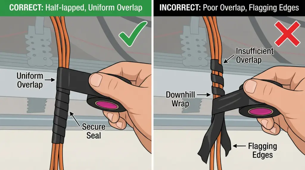
Wrap geometry planning prevents problems before they start. Always wrap “uphill”—from smaller diameter to larger—so that each layer’s edge is pressed down by the next wrap, reducing the tendency for edges to lift. For splices where conductors join at different angles or sizes, start at the smallest cross-section and work toward the largest, maintaining even tension. Plan the termination point: the last wrap should land where it can be applied with zero tension to prevent flagging (the tape end lifting and unraveling over time).
In automotive work, match the tape selection to the installation zone. Passenger compartment harnesses can use standard 105°C tapes; engine compartment applications demand tapes rated for 125°C or higher with enhanced abrasion resistance. Consult manufacturer guidelines (Tesa, 3M, Plymouth) for zone-specific tape recommendations, and verify that surfaces are dry and dust-free before application—moisture trapped under tape accelerates corrosion in automotive harnesses.
Proper preparation—correct splicing, padding irregular shapes, planning wrap direction and termination—takes minutes but determines whether the wrap lasts six months or twenty years.
Step-by-Step Application Technique
Proper wrapping technique transforms a roll of tape into a code-compliant, long-lasting insulation barrier. The fundamentals—half-lapped layers, controlled tension, uphill wrapping—apply whether you’re insulating a 600-volt branch circuit splice or protecting an automotive wire harness.
Standard Vinyl Electrical Tape Application
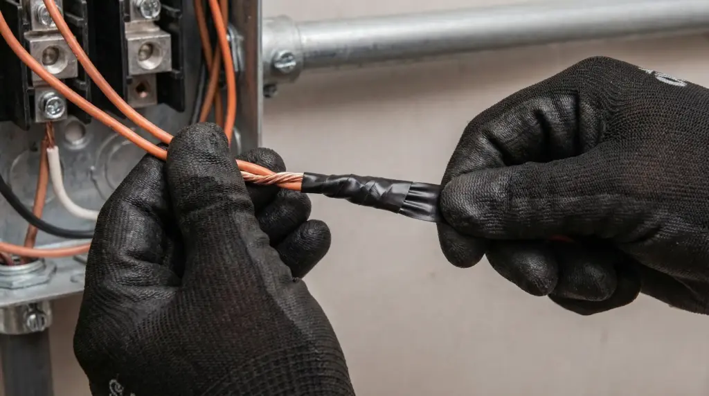
Step 1: Prepare the splice
Ensure the electrical connection is mechanically sound and electrically compliant (wire connectors, solder, or crimp per NEC 110.14(B)). Pad any irregular shapes—pigtail ends, hex wire nuts, crimp barrels—with electrical putty or a layer of rubber tape to eliminate voids and cushion sharp edges. Wipe the splice area clean and dry.
Step 2: Start on the smaller diameter, wrap uphill
Begin wrapping at the smallest cross-section of the splice. Anchor the tape with one full wrap, then proceed toward the larger diameter. This “uphill” direction keeps wrap edges pressed down by subsequent layers, reducing lift and improving the seal.
Step 3: Apply tension to achieve half-lap coverage
As you wrap, apply steady tension—enough to narrow the tape to about 5/8 of its original width and conform it tightly to the splice, but not so much that the tape thins excessively or distorts. Overlap each wrap by 50% (half the tape width), so every point on the splice receives at least two layers of PVC backing. This half-lap technique is specified in CSA C22.2 No. 197 and manufacturer guidelines; it ensures adequate dielectric thickness and mechanical protection.
Step 4: Maintain uniform coverage, avoid gaps
Keep wraps snug and evenly spaced. Gaps between wraps create weak points and moisture ingress paths. If wrapping a pigtail termination (wire ends sticking out), extend the tape beyond the ends, fold it back, and overwrap to create a protective cushion that resists cut-through.
Step 5: Terminate with zero tension
When you reach the end of the splice area, apply the final wrap with no tension—just lay it down gently. This prevents the tape end from pulling back and flagging (lifting and unraveling). Press the end firmly to ensure good adhesion.
Minimum layer count: For primary insulation on 600-volt branch circuits rated 80°C and below, apply at least two half-lapped layers. For higher-voltage splices or harsher environments, follow manufacturer recommendations—often three or more layers. Remember that “half-lapped” means each wrap covers half the previous wrap’s width, so two half-lapped layers deliver four thicknesses of tape at most points along the splice.
Rubber Splicing Tape and Mastic Application
Rubber splicing tapes (such as 3M Scotch 23 or 130C) and mastic tapes create moisture-tight primary insulation by fusing under stretch into a solid, homogeneous layer. They’re used for high-voltage splices, wet locations, and applications where a true moisture seal is critical.
Step 1: Stretch to fuse
Apply rubber tape in half-lapped layers while stretching it to between 50% and 75% of its original width. This stretch activates the self-bonding adhesive, causing successive wraps to fuse together into a unified insulation layer with no delamination planes. The tape should feel tight and conform closely to the splice.
Step 2: Control thickness for heat dissipation
Don’t overbuild. Excessive thickness traps heat around connectors, which can accelerate insulation aging and conductor overheating. Install only the thickness required to meet the voltage rating and allow proper heat dissipation—manufacturer datasheets specify minimum wrap counts for given voltage levels.
Step 3: Finish the wrap cleanly
At the end of the wrap, thin the tape end by pressing it flat with your palm or the heel of your hand, stretching it slightly so it nests into the existing wrap. This prevents the end from lifting.
Step 4: Overwrap with vinyl tape (if required)
Rubber splicing tape provides the electrical insulation and moisture seal, but it lacks UV resistance and flame retardancy. For outdoor installations or applications requiring mechanical protection, overwrap the rubber layer with at least two half-lapped layers of vinyl electrical tape. The vinyl serves as a protective jacket, shielding the rubber from sunlight, cold, and abrasion.
Wet Location and Submerged Splice Technique
For splices that will be submerged or exposed to standing water, use a layered approach:
- Inner moisture seal: Wrap with rubber mastic or self-fusing rubber tape in half-lapped layers under stretch. This creates a waterproof, self-bonding barrier.
- Outer protection jacket: Overwrap with vinyl electrical tape (minimum two half-lapped layers) for UV resistance, flame rating, and mechanical durability.
Vinyl tape alone is not sufficient for submerged applications—it protects against moisture vapor and splash, but the adhesive can eventually allow water to wick under the wrap in continuous immersion. The rubber or mastic inner layer provides the true water seal; vinyl is the protective outer jacket.
Special Considerations for Automotive Harnessing
Automotive wire harness wrapping follows the same half-lap and uphill principles but adds zone-specific requirements:
- Passenger compartment: Use tapes rated to 105°C, often cloth-backed or PVC for noise damping and abrasion resistance.
- Engine compartment: Use high-temperature tapes rated to 125°C or higher, with enhanced abrasion and fluid resistance.
- Underbody/chassis: Choose tapes with moisture and road salt resistance; consider fleece-backed or adhesive-coated cloth tapes for vibration damping and abrasion protection.
Always ensure surfaces are dry and free of assembly lubricants before wrapping. Automotive harnesses flex and vibrate; proper tension and half-lap coverage prevent tape loosening and harness chafing over time.
Common Mistakes and How to Avoid Them

Most electrical tape failures trace back to a handful of preventable mistakes. Recognizing these errors and correcting them before they cause problems separates reliable work from callbacks and safety hazards.
Insufficient Overlap or Layer Count
Applying tape with less than 50% overlap (half-lap) or using only a single layer leaves gaps and inadequate dielectric thickness. CSA C22.2 No. 197 and manufacturer specifications call for half-lapped application; this isn’t a suggestion—it’s the validated technique that delivers the rated insulation performance. A single layer stretched tight may look neat, but it provides only half the intended dielectric strength and leaves seams that can admit moisture.
Fix: Always apply at least two half-lapped layers for branch circuit splices rated up to 600 volts. For higher voltages or harsh environments, add more layers per manufacturer guidelines. If you’re unsure, err on the side of an extra layer—overbuilding slightly is safer than underbuilding.
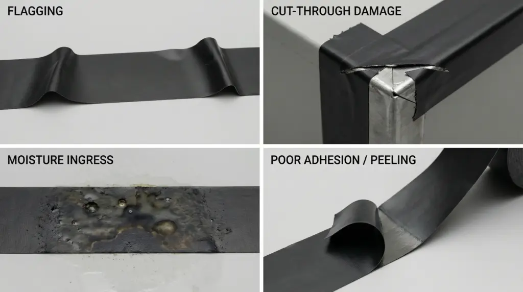
Overstretching the Last Wrap
Stretching the final wrap stores tension in the tape, causing it to contract after installation and pull the end free. This leads to flagging—the tape end lifts, unravels, and eventually the entire wrap loosens.
Fix: Apply the last wrap with zero tension. Lay it down gently, press it firmly into place, and ensure good adhesive contact. For rubber splicing tape, thin the end by pressing it flat and stretching slightly so it nests into the existing wrap without a raised edge.
Wrapping “Downhill”
Wrapping from larger diameter to smaller diameter (downhill) encourages wrap edges to lift. Each layer’s edge sits on top of the previous wrap rather than being pressed down by the next, creating mechanical weak points and moisture ingress paths.
Fix: Always start at the smallest cross-section and wrap “uphill” toward the larger diameter. This simple directional choice dramatically improves edge adhesion and seal integrity.
Using Vinyl Tape as the Only Layer in Wet Environments
Vinyl electrical tape resists moisture vapor and splash, but the rubber adhesive can eventually allow water to wick underneath in continuous immersion or submerged applications. Relying on vinyl alone in wet locations invites corrosion and tracking failures.
Fix: Use rubber mastic or self-fusing rubber splicing tape as the inner moisture seal, then overwrap with vinyl as the outer protective jacket. The rubber layer stops water; the vinyl protects the rubber from UV, cold, and mechanical damage.
Overbuilding Rubber Insulation
Applying excessive layers of rubber splicing tape around connectors traps heat, preventing proper thermal dissipation. Conductors and connectors generate heat under load; insulation that’s too thick accelerates aging and can lead to overheating failures.
Fix: Follow manufacturer datasheets for minimum wrap counts at your voltage level. Install only the thickness required to meet the electrical rating and allow heat to escape. Thicker isn’t always better.
Ignoring Irregular Connector Shapes
Wrapping tape directly over hex wire nuts, crimp barrel edges, or pigtail wire ends concentrates stress at sharp points, leading to cut-through and premature tape failure.
Fix: Pad irregular shapes before wrapping. Use electrical putty (3M Scotchfil) or a layer of rubber tape to fill voids and round off sharp edges. This cushion distributes stress and improves the seal. For pigtails, extend the wrap beyond the wire ends, fold back, and overwrap to create a protective cap.
Poor Surface Preparation
Dust, oils, assembly greases, and moisture interfere with adhesive bonding, reducing initial tack and long-term hold. In automotive applications, residual underbody coatings or assembly lubricants are common culprits.
Fix: Wipe surfaces clean and dry before applying tape. In automotive work, use isopropyl alcohol or an approved solvent to remove greases and films. A few seconds of cleaning prevents hours of rework.
Safety Considerations and Code Compliance
Electrical tape is a tool for code-compliant insulation and mechanical protection—not a shortcut around proper splicing methods or a substitute for listed devices. Understanding when tape is appropriate, which standards govern its use, and what the code actually requires keeps work safe and legal.
UL and CSA Listings: What They Mean
A UL or CSA listing isn’t just a marketing badge—it’s third-party verification that the tape meets standardized performance benchmarks. UL 510 (U.S.) and CSA C22.2 No. 197 (Canada) define test protocols for dielectric breakdown under dry, high-temperature, and humid conditions, along with adhesion, tensile strength, flammability, and aging resistance.
When you see “UL Listed Insulating Tape, Category OANZ/7, 80°C” on a product, you know:
- The tape has passed UL 510 dielectric, flame, and mechanical tests.
- It’s validated for field use on joints and splices.
- The 80°C (or 90°C, 105°C) rating defines the maximum continuous operating temperature.
- It meets conditions of acceptability for voltage and environmental exposure specified in the listing.
CSA C22.2 No. 197 tapes are intended for application in half-lapped layers to insulate joints and splices up to 1000 volts per the Canadian Electrical Code, Part I. Verify your tape’s listing and temperature rating before use—unlisted or misapplied tape voids warranty coverage and creates liability.
When Tape Is Appropriate vs. Wire Nuts or Heat Shrink
Electrical tape provides insulation over a splice; it does not create the splice. NEC 110.14(B) requires conductors to be spliced with devices identified for the use (twist-on wire connectors, push-in connectors, crimp sleeves) or by brazing, welding, or soldering with fusible metal. After the splice is mechanically and electrically sound, it must be covered with insulation equivalent to the conductors or with an identified insulating device.
Tape serves as that insulating cover. It’s appropriate when:
- The splice has been made with a listed device (wire nut, crimp, solder).
- You need to restore the wire’s insulation jacket over the connection.
- The environment and voltage are within the tape’s ratings.
Tape is not appropriate as:
- A standalone splicing method (wrapping bare wires together without a listed connector).
- Primary insulation for direct burial connections (unless the splice device itself is listed for direct burial and tape is part of the manufacturer’s installation instructions).
- A permanent repair for damaged cord insulation on flexible cords and extension cords subject to flexing and abrasion (heat shrink tubing or cord replacement is preferred).
Heat shrink tubing offers a neater, more durable finish for permanent splices where appearance and abrasion resistance matter, but it requires a heat source and advance planning (slip the tubing on before splicing). Tape is faster, requires no tools beyond the roll itself, and is ideal for field repairs and service work.
Voltage and Temperature Limits
Common vinyl electrical tapes are rated for splices and joints up to 600 volts (some CSA-listed products up to 1000 volts). Exceeding this voltage rating increases the risk of dielectric breakdown, tracking, and arc faults. For medium- or high-voltage work (above 600 V), use rubber splicing tapes and follow manufacturer specifications for layer count and application technique.
Temperature limits define the safe operating envelope. A tape rated UL 510, 80°C, is validated for continuous exposure up to 80°C; using it in a 105°C environment (such as a conductor rated 90°C under load or an automotive engine compartment) invites adhesive softening, backing degradation, and eventual failure. Match the tape’s temperature rating to the conductor’s insulation rating and the ambient environment.
Environmental Considerations: Automotive and Outdoor Applications
Automotive installations add zone-specific safety requirements:
- Passenger compartment: Tapes must meet FMVSS 302 flammability limits. Use tapes rated to 105°C minimum.
- Engine compartment: Requires tapes rated to 125°C or higher with fluid resistance (oil, coolant, fuel) and abrasion protection. Verify manufacturer specifications for under-hood use.
- Underbody/chassis: Exposure to moisture, road salt, and vibration demands tapes with closed-cell backing or moisture-resistant adhesive systems.
Outdoor and wet location splices require moisture sealing beyond what vinyl tape alone provides. Use rubber mastic or self-fusing rubber tape as the inner seal, then overwrap with vinyl for UV and mechanical protection.
Liability, Warranty, and Code Enforcement
Using listed tapes per manufacturer instructions and code requirements protects you legally and professionally. Unlisted tapes, improper application (insufficient layers, wrong voltage rating), or using tape as a substitute for listed splicing devices creates liability if a failure causes property damage, injury, or fire. Inspectors can—and do—red-tag work that doesn’t meet NEC or local code; rework costs time and reputation.
For professional electricians and contractors, specifying UL- or CSA-listed tapes and documenting compliance with installation guidelines is part of warranty coverage and quality assurance. For DIY homeowners, using listed products and following instructions is the best way to ensure safe, reliable repairs that won’t come back to haunt you.
Troubleshooting Failed Applications

When a tape wrap fails—flagging, telescoping, cut-through, moisture ingress—the root cause usually traces to one of a few common issues. Diagnosing the failure and applying the correct fix prevents recurrence.
Flagging (Edge Lift and Unraveling)
Symptom: The tape end lifts and begins to unravel, often pulling the entire wrap loose over time.
Cause: The final wrap was applied with tension, storing elastic energy that contracts the tape after installation. As the tape shrinks, it pulls the end free. Poor adhesion due to contaminated surfaces or cold application temperatures can also contribute.
Fix: Remove the failed wrap. Clean the splice area and allow it to reach room temperature if cold. Rewrap using proper technique—half-lapped layers, steady tension during wrapping, and zero tension on the final wrap. Press the final wrap firmly into place. For rubber splicing tape, thin the end by pressing flat so it nests into the existing wrap without a raised edge.
Telescoping (Sideways Shifting on the Roll or Splice)
Symptom: The tape layers slide sideways relative to each other, either on the roll during storage or on the splice after installation.
Symptom: Caused by excessive tension during wrapping, heat exposure during or after installation, or prolonged storage at elevated temperatures that softens the adhesive and allows layers to creep.
Fix: For rolls showing telescoping, follow manufacturer storage guidelines (typically below 25°C, 50% relative humidity). For installed wraps, remove and rewrap with controlled tension—enough to conform and narrow the tape slightly, but not so much that it distorts or stores excessive elastic energy. If the splice will be exposed to elevated temperatures, choose a tape with a higher temperature rating.
Cut-Through at Sharp Edges
Symptom: The tape is punctured or torn at sharp points—wire nuts, crimp barrel edges, pigtail ends.
Cause: Wrapping directly over irregular shapes concentrates stress and allows sharp edges to penetrate the PVC backing, especially under vibration or flexing.
Fix: Remove the damaged wrap. Pad the irregular surfaces with electrical putty (3M Scotchfil) or a layer of rubber tape to fill voids and round off sharp corners. Rewrap over the cushioned surface. For pigtails, extend the tape beyond the wire ends, fold it back, and overwrap to create a protective cap that distributes stress.
Moisture Ingress on Wet or Submerged Splices
Symptom: Corrosion, tracking, or insulation failure on splices exposed to standing water or continuous immersion.
Cause: Vinyl electrical tape alone isn’t designed for submerged applications. The rubber adhesive can allow moisture to wick underneath over time, compromising the splice.
Fix: Remove the failed wrap and dry the splice thoroughly. Re-establish a moisture seal using rubber mastic or self-fusing rubber splicing tape as the inner layer, applied in half-lapped wraps under stretch. Overwrap with vinyl electrical tape (minimum two half-lapped layers) to provide UV resistance, flame rating, and mechanical protection. The rubber layer provides the waterproof seal; vinyl is the protective jacket.
Poor Adhesion or Wrap Loosening Over Time
Symptom: The tape peels off easily, leaves little adhesive residue, or loosens after weeks or months in service.
Cause: Contaminated surfaces (oil, grease, dust), application in cold temperatures (below the tape’s conformability limit), or use of low-quality tape with poor adhesive formulation.
Fix: Clean surfaces thoroughly before rewrapping—wipe with isopropyl alcohol in automotive applications to remove greases and coatings. Allow substrates to reach room temperature or warmer before applying tape; cold surfaces reduce initial tack. Choose quality, UL- or CSA-listed tapes from reputable manufacturers (3M, Plymouth, Tesa); the cost difference is negligible compared to the labor of rework.
Conclusion
Electrical insulating tape is a deceptively simple tool backed by material science, standards testing, and decades of field validation. Its working principle—a high-dielectric-strength PVC backing bonded by pressure-sensitive adhesive to create a continuous, gap-free barrier—delivers reliable insulation when applied correctly. The difference between a wrap that lasts and one that fails comes down to understanding the material properties, following proven installation techniques, and respecting the voltage, temperature, and environmental limits.
Half-lapped layers, uphill wrapping, controlled tension, and zero-tension termination aren’t arbitrary—they’re the validated methods that manufacturers and standards bodies specify to achieve rated performance. Padding irregular shapes, cleaning surfaces, and matching tape ratings to application demands prevent the majority of field failures. Whether you’re a DIY homeowner repairing a lamp cord, an electrician making code-compliant branch circuit splices, or an automotive technician rebuilding a harness, these principles apply.
Choose UL- or CSA-listed tapes appropriate to your voltage and environment. Follow manufacturer installation instructions. Recognize when tape is appropriate and when wire nuts, crimp connectors, or heat shrink tubing are better choices. The materials work; the technique matters. Get both right, and the splice will outlast the conductors it protects.