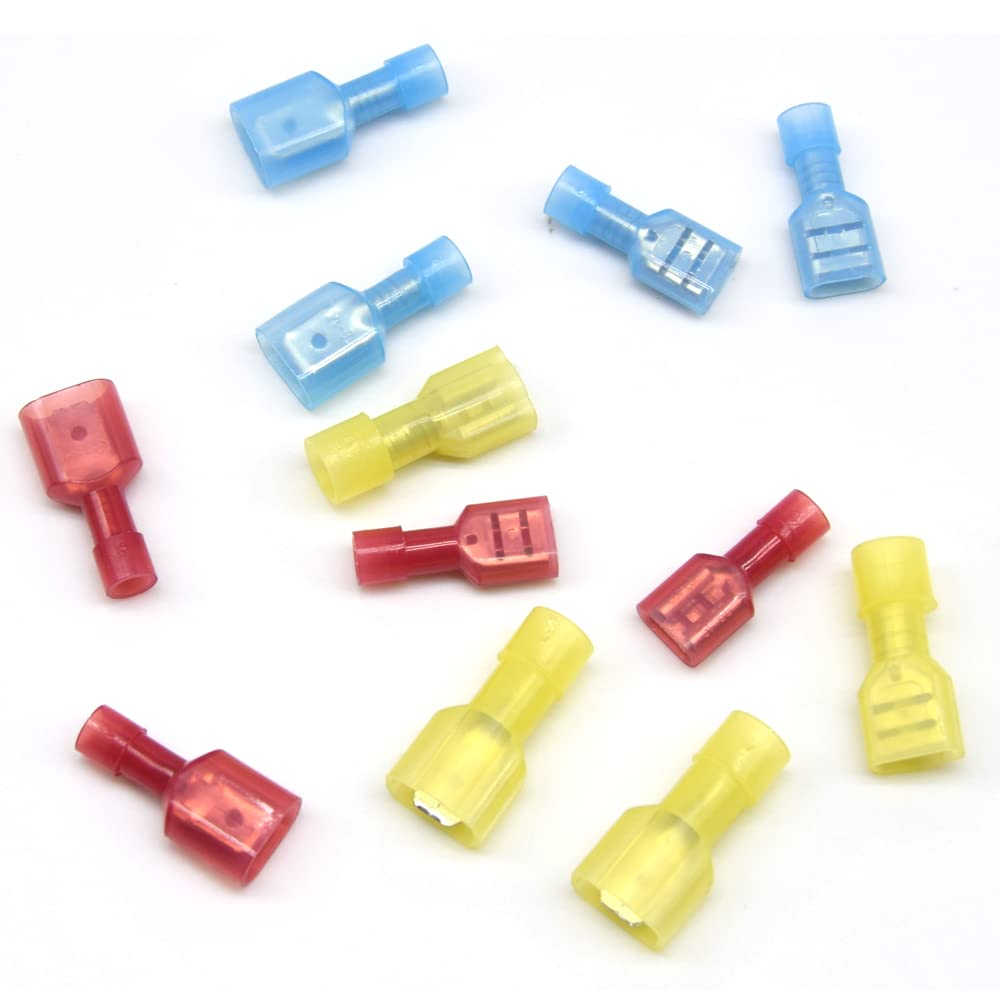
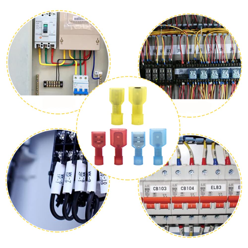
Male and female wire connectors are electrical connection components where male connectors feature protruding pins or contacts that insert into female connectors with corresponding receptacles or holes. This fundamental pairing system ensures secure, reliable electrical connections across virtually every electrical and electronic application from household wiring to industrial machinery.
Understanding the difference between male and female connectors is crucial for anyone working with electrical systems, whether you’re a professional electrician, engineer, or DIY enthusiast. This guide provides comprehensive coverage of connector types, applications, selection criteria, and safety considerations.
What Are Male and Female Wire Connectors?

Male Wire Connectors (Plug Connectors)
Male connectors, also called plug connectors, feature protruding metal pins, contacts, or prongs that extend outward from the connector body. These pins are designed to insert into corresponding receptacles on female connectors.
Key characteristics of male connectors:
- Exposed metal contacts or pins
- Typically the “input” side of a connection
- Often found on power cords and cable ends
- Generally considered the “hot” or powered side
Female Wire Connectors (Socket/Receptacle Connectors)
Female connectors, also known as socket or receptacle connectors, contain recessed holes, slots, or receptacles that receive and secure the pins from male connectors.
Key characteristics of female connectors:
- Recessed contact points for safety
- Typically the “output” or receiving side
- Often found on outlets and equipment panels
- Generally the “load” or unpowered side for safety
Expert Tip: The male/female designation follows the principle that the powered conductor (male) inserts into the protected receptacle (female) to minimize electrical shock risk.
Key Differences Between Male and Female Connectors
| Feature | Male Connector | Female Connector |
|---|---|---|
| Contact Design | Protruding pins/prongs | Recessed receptacles/holes |
| Safety Level | Higher shock risk (exposed) | Lower shock risk (protected) |
| Typical Application | Input/plug side | Output/socket side |
| Power Status | Usually powered/hot | Usually load/receiving |
| Mounting | Often on cables/cords | Often panel or wall mounted |
| Mechanical Protection | Contacts exposed | Contacts protected |
| Industry Standard | IEC 60320, NEMA configurations | IEC 60320, NEMA configurations |
Types of Male and Female Wire Connectors
Power Connectors
AC Power Connectors
NEMA 5-15 (Standard US Household)
- Male: 3-prong plug with flat parallel blades + ground
- Female: Standard wall outlet receptacle
- Application: 15A, 125V household devices
- Safety Note: Female design prevents accidental contact with live conductors
IEC C13/C14 (Computer Power)
- Male (C14): 3-pin inlet connector
- Female (C13): 3-socket power cord connector
- Application: Computer equipment, 10A rating
- Advantage: Keyed design prevents incorrect insertion
DC Power Connectors
Barrel Connectors
- Male: Center pin with outer sleeve contact
- Female: Center hole with outer ring contact
- Sizes: 2.1mm, 2.5mm, 5.5mm common diameters
- Application: Low-voltage DC devices, adapters
Signal Connectors
Audio/Video Connectors
RCA Connectors
- Male: Center pin with outer shield ring
- Female: Center socket with outer ground ring
- Color coding: Red (right audio), White (left audio), Yellow (video)
- Application: Consumer audio/video equipment
XLR Connectors
- Male (XLR-M): 3 protruding pins in circular arrangement
- Female (XLR-F): 3-hole receptacle socket
- Application: Professional audio, microphones, stage lighting
- Advantage: Locking mechanism prevents accidental disconnection
Data Connectors
USB Connectors
- USB-A Male: Flat rectangular plug with 4 contacts
- USB-A Female: Rectangular receptacle socket
- USB-C: Reversible design, both male and female variants
- Application: Data transfer, device charging
Specialized Industrial Connectors
Twist-Lock Connectors (NEMA L-Series)
- Male: Curved prongs with locking mechanism
- Female: Corresponding curved receptacles
- Application: Industrial equipment requiring secure connections
- Safety Feature: Cannot be accidentally disconnected
Applications and Use Cases

Residential Applications
Power Distribution
- Wall outlets (female) and plug-in devices (male)
- Extension cords with male plugs and female sockets
- Appliance connections and power strips
Low-Voltage Systems
- Thermostat wiring with male/female quick-connects
- Doorbell transformers and chime connections
- Security system sensor connections
Commercial and Industrial Applications
Motor Control Systems
- Control panel connections with male pins to female receptacles
- Variable frequency drive (VFD) connections
- Emergency stop circuit connections
Data and Communication
- Network patch panels (female) with patch cables (male)
- Telecommunications equipment connections
- Industrial Ethernet and fieldbus connections
Power Distribution
- Electrical panel connections
- Three-phase motor connections
- High-amperage industrial equipment
Automotive Applications
Engine Management
- ECU connectors with male pins to female receptacles
- Sensor connections (oxygen, temperature, pressure)
- Fuel injector connections
Lighting Systems
- Headlight and taillight connections
- Dashboard instrument connections
- Trailer wiring harnesses
Safety Warning: Always ensure power is disconnected before making or breaking electrical connections. Follow lockout/tagout procedures in industrial settings.
How to Choose the Right Male and Female Connectors
Electrical Specifications
Current Rating
- Match connector amperage rating to circuit requirements
- Include 25% safety margin for continuous loads
- Consider temperature derating factors
Voltage Rating
- Ensure connector voltage rating exceeds system voltage
- Consider peak voltages and transient conditions
- Account for altitude derating if applicable
Contact Resistance
- Lower resistance reduces heat generation
- Critical for high-current applications
- Specify maximum milliohm values for precision circuits
Environmental Considerations
IP Rating (Ingress Protection)
- IP65: Dust-tight, water jet resistant
- IP67: Dust-tight, temporary immersion resistant
- IP68: Dust-tight, continuous immersion capable
Temperature Range
- Operating temperature: -40°C to +125°C typical
- Storage temperature: Often wider range than operating
- Consider thermal cycling effects
Chemical Resistance
- Evaluate exposure to oils, solvents, cleaning agents
- Select appropriate housing materials (nylon, PVC, fluoropolymers)
- Consider UV resistance for outdoor applications
Mechanical Requirements
Mating Cycles
- Connector lifecycle rating (500, 1000, 10000+ cycles)
- Consider maintenance frequency and accessibility
- Balance cost vs. durability requirements
Vibration and Shock
- Automotive: SAE J1128 standard requirements
- Industrial: IEC 60068 environmental testing standards
- Aerospace: DO-160 environmental conditions
Selection Criteria Table
| Application Type | Recommended Features | Key Considerations |
|---|---|---|
| Household Power | NEMA 5-15, UL listed | Safety, code compliance |
| Industrial Control | IP67, twist-lock | Vibration resistance, safety |
| Automotive | Sealed, automotive grade | Temperature, vibration, chemicals |
| Data/Telecom | Shielded, high-speed rated | Signal integrity, bandwidth |
| Audio/Video | Gold-plated contacts | Signal quality, corrosion resistance |
| Outdoor | IP65+, UV resistant | Weather protection, longevity |
Installation Best Practices
Preparation Steps
- Power isolation: Verify zero energy state using lockout/tagout procedures
- Wire preparation: Strip insulation to manufacturer specifications
- Connector inspection: Check for damage, corrosion, or contamination
- Tool preparation: Ensure proper crimping tools are calibrated
Connection Process
- Wire insertion: Follow manufacturer’s wire gauge and insertion depth requirements
- Crimping technique: Use proper die size and apply consistent pressure
- Pull testing: Verify connections meet specified pull-out force requirements
- Insulation check: Ensure no exposed conductors outside connector body
Quality Verification
- Visual inspection: Check for proper crimp formation and wire alignment
- Electrical testing: Verify continuity and resistance values
- Mechanical testing: Confirm proper mating force and retention
- Environmental testing: Validate IP rating if required
Expert Tip: Use a crimping tool specifically designed for your connector type. Generic tools often result in poor connections and premature failure.
Safety Considerations and Code Compliance
National Electrical Code (NEC) Requirements
Article 110.14 – Electrical Connections
- Connections must be made with approved pressure connectors
- Dissimilar metals require compatible connection methods
- Temperature ratings must be observed
Article 400 – Flexible Cords and Cables
- Male plugs on flexible cords must be polarized when required
- Attachment plugs must be constructed per UL standards
- Cord sets must have proper strain relief
Safety Protocols
Personal Protective Equipment (PPE)
- Safety glasses when working with electrical connections
- Insulated tools rated for system voltage
- Arc-rated clothing for energized work (when permitted)
Hazard Identification
- Arc flash risk: Calculate incident energy for energized work
- Shock hazard: Identify exposed conductors and energy sources
- Mechanical hazards: Rotating equipment and pinch points
Professional Installation Requirements
Licensed Electrician Required For:
- Permanent wiring connections above 50V
- Commercial and industrial power distribution
- Life safety systems (fire alarm, emergency lighting)
Permit Requirements:
- Building electrical permits for permanent installations
- Inspection requirements for code compliance verification
- Certificate of occupancy dependencies
Troubleshooting Common Issues
Connection Problems
Poor Contact/High Resistance
- Symptoms: Overheating, voltage drop, intermittent operation
- Causes: Corrosion, loose connections, incompatible materials
- Solutions: Clean contacts, re-terminate connections, verify torque specifications
Mechanical Failure
- Symptoms: Loose connections, damaged housing, bent pins
- Causes: Excessive force, wrong connector type, wear
- Solutions: Replace damaged components, verify mating procedures
Environmental Degradation
Corrosion
- Prevention: Use appropriate IP ratings, conformal coatings
- Treatment: Clean with contact cleaner, apply protective compounds
- Long-term: Consider upgraded materials (stainless steel, gold plating)
UV Damage
- Prevention: UV-stabilized housings, protective enclosures
- Identification: Brittleness, discoloration, cracking
- Remediation: Replace deteriorated components
Frequently Asked Questions
What makes a connector male vs female?
A connector is male if it has protruding pins or contacts that insert into another connector. A connector is female if it has receptacles or holes that receive the male connector’s pins. This design principle prioritizes safety by keeping powered conductors (typically male) protected when disconnected.
Can I connect male to male or female to female connectors?
No, male and female connectors are specifically designed to mate only with their opposite gender. Male-to-male or female-to-female connections require adapters or gender changers, which should only be used when electrically safe and mechanically appropriate.
Why are power outlets female instead of male?
Power outlets are female for safety – the live electrical contacts are recessed and protected, reducing the risk of accidental contact. Male plugs on cords minimize shock hazard since the dangerous conductors are only exposed when being inserted into the protected female outlet.
How do I identify the gender of a connector without seeing the contacts?
Check the connector housing design: male connectors typically have a protruding center section or pins visible through the housing, while female connectors have recessed openings or holes. Manufacturer part numbers often include “M” for male or “F” for female designations.
What happens if I force incompatible connectors together?
Forcing incompatible connectors can cause permanent damage including bent pins, cracked housings, or destroyed contact surfaces. This can create safety hazards including poor connections, arcing, or fire risks. Always verify connector compatibility before attempting connections.
Are there universal male and female connector standards?
Yes, several international standards exist including IEC 60320 for power connectors, USB standards for data connections, and NEMA standards for North American power connections. However, many specialized applications use proprietary connector designs for specific performance requirements.
How often should connectors be inspected or replaced?
Inspection frequency depends on the application environment and criticality. Industrial connectors in harsh environments may require monthly inspection, while household connectors might only need inspection during electrical maintenance. Replace connectors showing signs of damage, corrosion, overheating, or mechanical wear.
Can I use indoor connectors for outdoor applications?
No, outdoor applications require connectors with appropriate IP ratings for weather protection. Indoor connectors lack the sealing and UV resistance needed for outdoor environments, leading to premature failure and potential safety hazards.
Quick Reference Guide
Connector Selection Checklist
- Electrical ratings match or exceed requirements
- Environmental protection appropriate for application
- Mechanical specifications meet durability needs
- Industry standards and code compliance verified
- Safety features appropriate for user access level
- Installation tools and expertise available
- Maintenance accessibility considered
- Total cost of ownership evaluated
Common Wire Gauge to Connector Ratings
| Wire Gauge (AWG) | Current Rating | Typical Connector Types |
|---|---|---|
| 18 AWG | 7-10A | Small appliance, electronics |
| 16 AWG | 10-13A | Extension cords, power tools |
| 14 AWG | 15A | Household circuits, outlets |
| 12 AWG | 20A | Heavy appliances, HVAC |
| 10 AWG | 30A | Electric dryers, welders |
Conclusion
Male and female wire connectors form the foundation of safe, reliable electrical connections across all industries and applications. The male connector’s protruding pins mate with the female connector’s protective receptacles, creating a secure electrical and mechanical connection while maintaining safety through proper design.
Key takeaways for connector selection:
- Match electrical ratings to application requirements with appropriate safety margins
- Select environmental protection levels appropriate for installation conditions
- Prioritize safety through proper gender selection and code-compliant installation
- Consider total cost of ownership including maintenance and replacement cycles
Whether you’re selecting connectors for a simple household repair or designing complex industrial systems, understanding male and female connector principles ensures safe, reliable, and code-compliant electrical connections.
Professional Recommendation: For critical applications or high-voltage systems, consult with a qualified electrical engineer or licensed electrician to ensure proper connector selection and installation procedures.

