
Solder sleeve heat shrink connectors provide waterproof, permanent wire connections by combining solder rings with heat-activated shrink tubing in a single component. You simply insert stripped wires, apply heat with a heat gun or torch, and the connector automatically solders while creating a sealed, insulated joint that meets marine and automotive industry standards.
Key Benefits: Waterproof sealing (IP67 rating), vibration resistance, corrosion protection, and professional-grade connections without requiring separate solder, flux, or heat shrink tubing.
What Are Solder Sleeve Heat Shrink Connectors?
Solder sleeve heat shrink connectors are pre-engineered electrical connectors that contain three essential components in one integrated unit:
- Heat shrink tubing (outer protective layer)
- Solder ring (internal connection material)
- Heat-activated adhesive (waterproof sealant)
When heated to 200-250°F (93-121°C), the solder melts to create electrical contact while the tubing shrinks and the adhesive flows to form a waterproof seal. These connectors eliminate the need for separate soldering operations and provide consistent, professional-grade results.
Industry Classifications:
- SAE Standards: J1128 automotive wire specifications
- Military Standards: MIL-DTL-23053 heat shrink requirements
- Marine Standards: ABYC E-11 electrical systems compliance
- UL Recognition: File E45960 for electrical safety
Key Differences: Solder Sleeves vs Traditional Connection Methods
| Connection Method | Waterproof Rating | Installation Time | Skill Level Required | Vibration Resistance | Cost per Connection |
|---|---|---|---|---|---|
| Solder Sleeves | IP67 (submersible) | 30-60 seconds | Beginner-Intermediate | Excellent | $0.50-$2.00 |
| Traditional Solder + Heat Shrink | IP65 (splash proof) | 3-5 minutes | Advanced | Good | $0.25-$0.75 |
| Wire Nuts | IP20 (indoor only) | 15 seconds | Beginner | Poor | $0.10-$0.25 |
| Crimp Connectors | IP54 (limited moisture) | 20 seconds | Intermediate | Good | $0.15-$0.50 |
| Butt Splice Connectors | IP40 (basic protection) | 10 seconds | Beginner | Fair | $0.05-$0.20 |
⚠️ Safety Note: Solder sleeve connectors are the only method providing true submersible waterproof protection suitable for marine and underground applications.
Applications and Use Cases
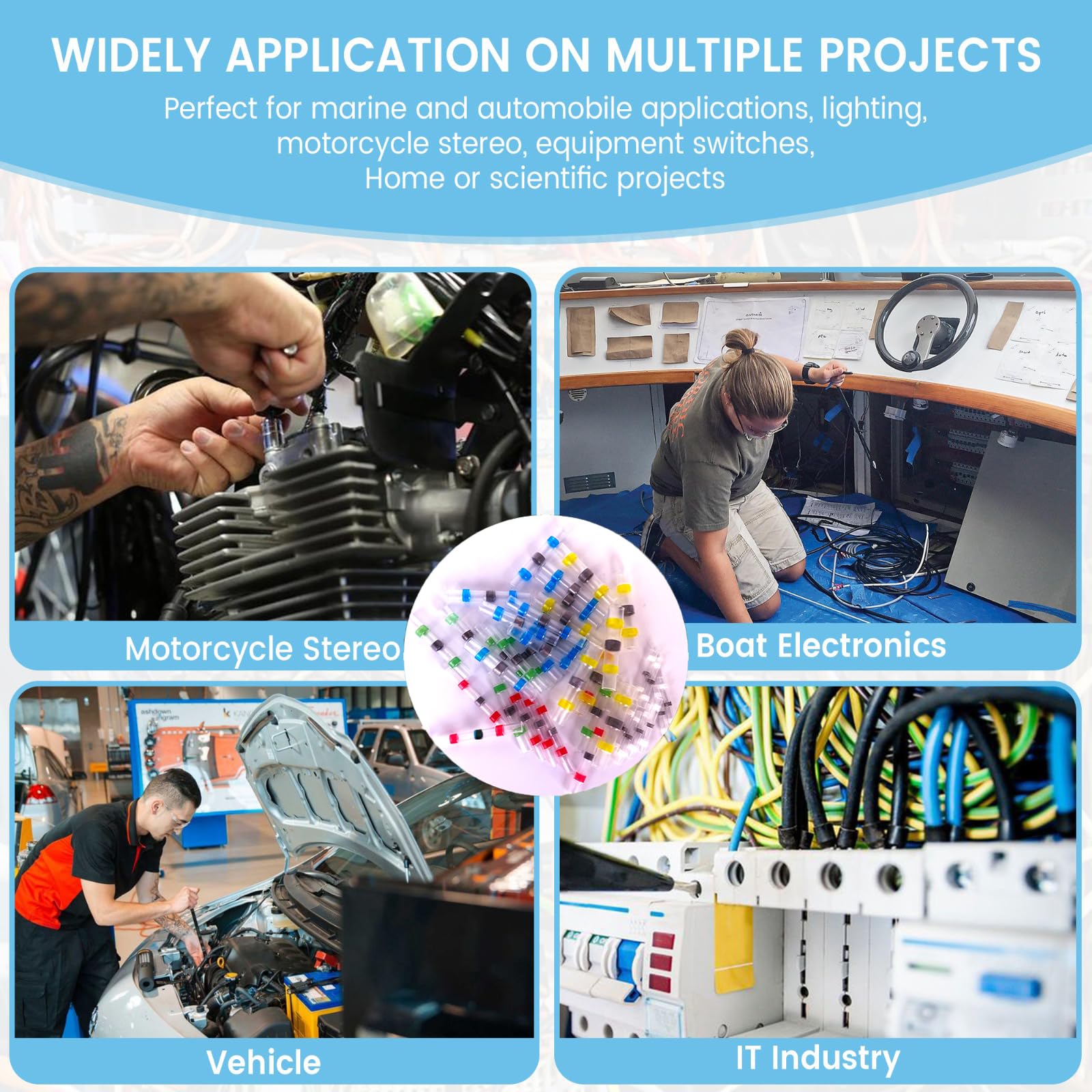
Marine and Boat Wiring
- Navigation light connections (meets USCG requirements)
- Bilge pump circuits (submersible protection required)
- Through-hull sensor wiring (saltwater corrosion resistance)
- Trailer light connections (repeated water immersion)
Automotive Applications
- Under-hood engine sensors (heat and moisture protection)
- Trailer brake connections (DOT compliance standards)
- Fuel pump wiring (vapor seal requirements)
- Headlight and taillight repairs (vibration resistance)
Professional Installation Scenarios
- Outdoor security cameras (weatherproof connections)
- Pool and spa equipment (submersible rated joints)
- Agricultural equipment (chemical and moisture resistance)
- HVAC condensate pump wiring (humidity protection)
How to Use Solder Sleeve Heat Shrink Connectors: Step-by-Step Process
Required Tools and Materials
Essential Equipment:
- Heat gun (1500W minimum) or butane torch
- Wire strippers (12-22 AWG capacity)
- Digital multimeter for testing
- Safety glasses and heat-resistant gloves
Professional Recommendations:
- Heat Gun: Wagner Furno 300 or equivalent (variable temperature control)
- Wire Strippers: Klein Tools 11063W (precise gauge markings)
- Multimeter: Fluke 117 (automotive-rated for safety)
Installation Process
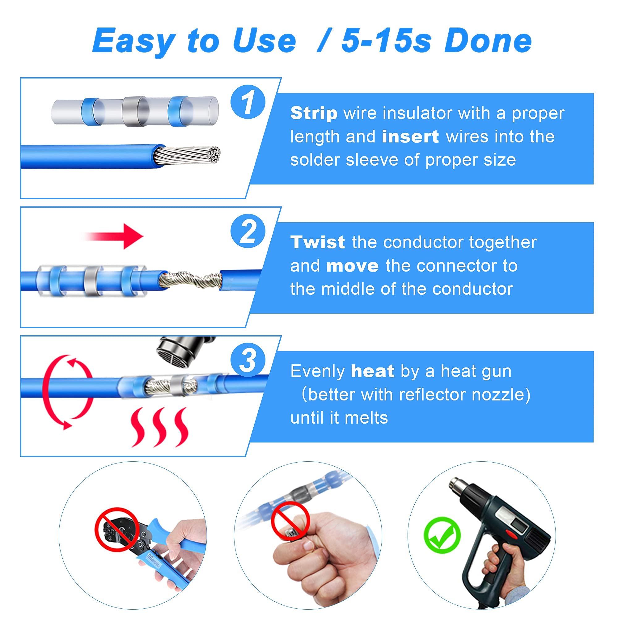
Step 1: Wire Preparation
- Cut wires cleanly using sharp wire cutters (no crushing or fraying)
- Strip insulation to exact connector length specification:
- Small connectors: 1/4 inch (6mm)
- Medium connectors: 3/8 inch (10mm)
- Large connectors: 1/2 inch (12mm)
- Clean copper strands with electrical contact cleaner if corroded
- Twist stranded wires clockwise to prevent spreading
⚠️ Critical Safety Warning: Never exceed specified strip lengths. Too much exposed copper creates short circuit risks; too little prevents proper solder contact.
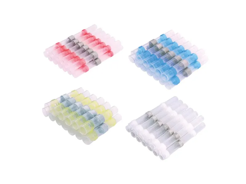
Step 2: Connector Selection and Positioning
- Match connector size to combined wire gauge:
- Red (22-18 AWG): Single or double small wires
- Blue (16-14 AWG): Medium gauge applications
- Yellow (12-10 AWG): Heavy-duty connections
- Insert wires completely into connector ends until copper touches internal solder ring
- Center the connection point within the connector for balanced heat distribution
Step 3: Heat Application Process
- Set heat gun temperature to 200-250°F (93-121°C)
- Apply heat evenly starting from center and moving outward
- Watch for visual indicators:
- Tubing begins shrinking (10-15 seconds)
- Solder ring becomes visible through clear window (15-20 seconds)
- Solder flows around wires (20-25 seconds)
- Adhesive appears at connector ends (25-30 seconds)
- Continue heating until adhesive fully seals both ends
- Remove heat source and allow 60 seconds cooling time
🔥 Heat Safety Protocol: Never use open flame near fuel vapors. Always wear safety glasses and heat-resistant gloves rated to 250°F minimum.
Step 4: Quality Verification
- Visual inspection: Confirm solder visibility through clear section
- Seal verification: Check adhesive flow at both connector ends
- Electrical testing: Verify continuity with digital multimeter
- Physical test: Gently tug wires to confirm mechanical strength
- Insulation check: Test insulation resistance (minimum 1 megohm)
Connector Size Selection Guide
Wire Gauge Compatibility Chart
| Connector Color | Wire Gauge Range | Maximum Current | Voltage Rating | Typical Applications |
|---|---|---|---|---|
| Red | 22-18 AWG | 15 Amps | 600V | Signal wires, small lights |
| Blue | 16-14 AWG | 25 Amps | 600V | Navigation lights, pumps |
| Yellow | 12-10 AWG | 40 Amps | 600V | Starting circuits, heavy loads |
Professional Selection Criteria
For Single Wire Connections:
- Choose connector one size larger than wire gauge for optimal fit
- Ensure 360-degree solder coverage around wire strands
- Verify current rating exceeds circuit protection by 25% minimum
For Multi-Wire Connections:
- Calculate total cross-sectional area of all wires
- Select connector size based on combined wire gauge equivalent
- Never exceed manufacturer’s wire quantity specifications
Common Problems and Troubleshooting
Issue: Incomplete Solder Flow
Symptoms: Solder visible on one side only, poor electrical connection
Causes: Insufficient heat, uneven heat application, contaminated wires
Solutions:
- Increase heat gun temperature to 250°F maximum
- Apply heat in circular motion around entire connector
- Clean wires with electrical contact cleaner before reconnection
Issue: Overheating and Damage
Symptoms: Burnt insulation, melted connector housing, wire damage
Causes: Excessive temperature, prolonged heat application
Solutions:
- Reduce temperature to 200°F and increase application time
- Use consistent motion to distribute heat evenly
- Replace damaged connector and wires completely
Issue: Poor Waterproof Seal
Symptoms: Moisture intrusion, corrosion at connection points
Causes: Insufficient adhesive flow, contaminated connector ends
Solutions:
- Ensure adhesive appears at both ends during heating
- Clean connector area before installation
- Apply additional marine-grade sealant if required
🔧 Professional Tip: When in doubt, cut and restart with a new connector. The cost of a connector is minimal compared to electrical system failures.
Safety Requirements and Code Compliance
Electrical Code Standards
- NEC Article 110: General requirements for electrical installations
- ABYC E-11: Marine electrical systems (boats and yachts)
- SAE J1128: Automotive low-voltage cable standards
- UL 486D: Splicing wire connectors for electrical safety
Installation Safety Protocol
- Power isolation: Disconnect all power sources before work
- Circuit verification: Test wires with multimeter to confirm de-energization
- Personal protection: Use safety glasses and insulated tools rated for voltage
- Environmental safety: Avoid installation in explosive atmospheres
- Professional consultation: Contact licensed electrician for high-voltage applications
⚠️ Code Compliance Warning: Some jurisdictions require licensed electrician installation for connections above 50 volts or in commercial applications. Check local electrical codes before proceeding.
Expert Tips and Professional Recommendations
Installation Best Practices
- Temperature monitoring: Use infrared thermometer to verify 200-250°F heat application
- Pre-staging: Organize all materials and tools before beginning work
- Quality connectors: Choose marine-grade connectors with clear inspection windows
- Documentation: Photograph completed connections for maintenance records
Long-Term Reliability Factors
- Strain relief: Provide adequate wire support to prevent mechanical stress
- Environmental protection: Consider additional conduit in harsh environments
- Regular inspection: Check connections annually for signs of degradation
- Replacement schedule: Replace connections every 5-7 years in marine applications
When to Call a Professional
Contact a certified marine electrician or automotive technician for:
- High-voltage systems (above 50 volts DC or any AC voltage)
- Critical safety circuits (navigation lights, bilge pumps, emergency systems)
- Insurance requirements (some policies require professional installation)
- Warranty considerations (equipment warranties may require certified installation)
Quick Reference Guide
Heat Application Quick Check
✅ Correct Process: Even heat application, 200-250°F, 30-60 seconds total
✅ Visual Confirmation: Solder visible, tubing shrunk, adhesive at ends
✅ Testing Complete: Continuity verified, insulation tested, physical strength confirmed
Troubleshooting Checklist
- Wires stripped to correct length specification
- Connector size matches wire gauge requirements
- Heat gun temperature verified with thermometer
- Solder flow visible through inspection window
- Adhesive seal present at both connector ends
- Electrical continuity confirmed with multimeter
Frequently Asked Questions
What makes solder sleeve connectors different from regular heat shrink?
Solder sleeve connectors contain an internal solder ring that automatically creates the electrical connection when heated, while regular heat shrink tubing only provides insulation over an existing soldered joint. This eliminates the need for separate soldering operations and flux application.
How long do solder sleeve connections last in marine environments?
When properly installed, solder sleeve connections typically last 7-10 years in marine environments before requiring replacement. Factors affecting lifespan include saltwater exposure, temperature cycling, and mechanical vibration.
Can you use solder sleeve connectors on solid core wire?
Yes, solder sleeve connectors work with both stranded and solid core wire within their specified gauge ranges. However, stranded wire provides better vibration resistance and is preferred for mobile applications like automotive and marine use.
What temperature range can solder sleeve connectors handle?
Most solder sleeve connectors are rated for continuous operation from -40°F to +200°F (-40°C to +93°C). For extreme temperature applications, specify high-temperature variants rated to 275°F (135°C).
Are solder sleeve connectors approved for underground burial?
Yes, when properly installed, solder sleeve connectors meet UL direct burial requirements and provide IP67 waterproof protection suitable for underground applications. Always verify local electrical code requirements before installation.
How do you remove a solder sleeve connector if needed?
Solder sleeve connectors are designed as permanent connections. Removal requires cutting the wires on both sides of the connector. The connection cannot be disassembled without destroying the connector.
What’s the minimum wire length needed for installation?
Allow minimum 2 inches of wire length beyond the connection point to accommodate the connector size and provide adequate working space. Longer wires are always preferable for professional installation flexibility.
Can multiple wires be connected in one solder sleeve?
Some solder sleeve connectors are designed for multi-wire connections, but never exceed the manufacturer’s specifications for wire quantity and total cross-sectional area. When in doubt, use separate connectors for each wire pair.
Professional Installation Services: For critical applications requiring certified installation, consult marine electricians certified by ABYC or automotive technicians with ASE electrical certification. Proper installation ensures safety, compliance, and warranty protection for your electrical systems.
