
Piggyback terminals are specialized electrical connectors that allow you to connect multiple wires to a single terminal point without removing the original connection. These terminals create a secure, stackable connection system that maintains circuit integrity while enabling circuit expansion or monitoring connections.
What Are Piggyback Terminals? Key Definitions

Piggyback Terminal: A two-piece electrical connector consisting of a male plug and female receptacle that allows one wire to connect to an existing terminal while providing a pass-through connection point for additional wires.
Key Components:
- Male Terminal: Insulated crimp terminal with protruding metal tab
- Female Terminal: Insulated receptacle terminal with internal spring contacts
- Wire Gauge Compatibility: Available for 22-10 AWG wire sizes
- Insulation Rating: Typically rated for 300V-600V applications
Piggyback vs. Standard Terminal Connections: Complete Comparison
| Feature | Piggyback Terminals | Standard Ring/Spade Terminals | Wire Nuts |
|---|---|---|---|
| Installation Method | Crimp and stack | Single crimp connection | Twist and cap |
| Removal Required | No disconnection needed | Must remove existing wire | Must untwist all wires |
| Connection Reliability | Excellent (double contact) | Excellent | Good (when properly installed) |
| Vibration Resistance | Superior | Good | Poor in mobile applications |
| Code Compliance | NEC compliant when rated | NEC compliant | Limited applications |
| Cost per Connection | Higher initial cost | Lower cost | Lowest cost |
| Inspection Capability | Visual inspection possible | Standard inspection | Hidden connection |
| Professional Grade | Yes | Yes | Residential primarily |
Primary Applications and Use Cases
1. Automotive Electrical Systems
- Trailer Connections: Adding trailer lighting circuits to existing tail light terminals
- Accessory Installation: Connecting aftermarket lights, horns, or electronic devices
- Diagnostic Access: Creating test points for electrical troubleshooting
- Safety Compliance: Maintaining original equipment manufacturer (OEM) connections
2. Industrial Control Panels
- Signal Monitoring: Adding instrumentation without disrupting control circuits
- Parallel Circuit Creation: Feeding multiple devices from single control points
- Maintenance Access: Creating disconnectable test points for circuit analysis
- Code Compliance: Meeting NEC Article 110.14 connection requirements
3. Marine Electrical Applications
- Navigation Equipment: Connecting GPS, fish finders, and communication devices
- Safety Systems: Adding bilge pump alarms and emergency lighting
- Corrosion Prevention: Minimizing connection points in marine environments
- Coast Guard Compliance: Meeting ABYC electrical standards
Step-by-Step Installation Process
Phase 1: Pre-Installation Safety
- De-energize the Circuit
- Turn off power at the main breaker
- Verify de-energization with multimeter
- Apply lockout/tagout procedures per OSHA standards
- Select Proper Terminal Size
- Match wire gauge to terminal specifications
- Verify voltage rating meets circuit requirements
- Check temperature rating for application environment
Phase 2: Terminal Preparation
- Strip Wire Insulation
- Remove exactly 1/4 inch of insulation
- Use proper wire stripping tools to prevent nicking
- Inspect conductor for damage or corrosion
- Insert Wire into Terminal
- Slide wire fully into crimp barrel
- Ensure no conductor strands extend beyond terminal
- Verify proper wire insertion before crimping
Phase 3: Crimping Process
- Apply Proper Crimp
- Use calibrated crimping tool rated for terminal type
- Position terminal in tool according to manufacturer specifications
- Apply single, complete crimp motion
- Inspect crimp for proper compression and conductor retention
Phase 4: Connection Installation
- Install Male Terminal
- Connect male terminal to new circuit wire
- Verify secure mechanical connection
- Test connection with gentle pull test
- Install Female Terminal
- Connect female terminal to tap-off wire
- Ensure complete insertion of male terminal into female receptacle
- Verify positive mechanical engagement
Safety Requirements and Code Compliance
⚠️ Critical Safety Warning
Never install piggyback terminals on energized circuits. Always verify de-energization with calibrated test equipment before beginning any electrical work.
National Electrical Code (NEC) Compliance
- Article 110.14: Connection requirements for electrical equipment
- Article 400.8: Flexible cord termination methods
- UL Listed: Use only UL Listed terminals for code compliance
- Temperature Rating: Must meet or exceed circuit operating temperature
Professional Installation Standards
- Torque Specifications: Follow manufacturer torque requirements
- Environmental Protection: Use terminals rated for installation environment
- Inspection Requirements: Visual inspection required before energization
- Documentation: Maintain installation records for inspection authority
Terminal Selection Criteria
Wire Gauge Compatibility Chart
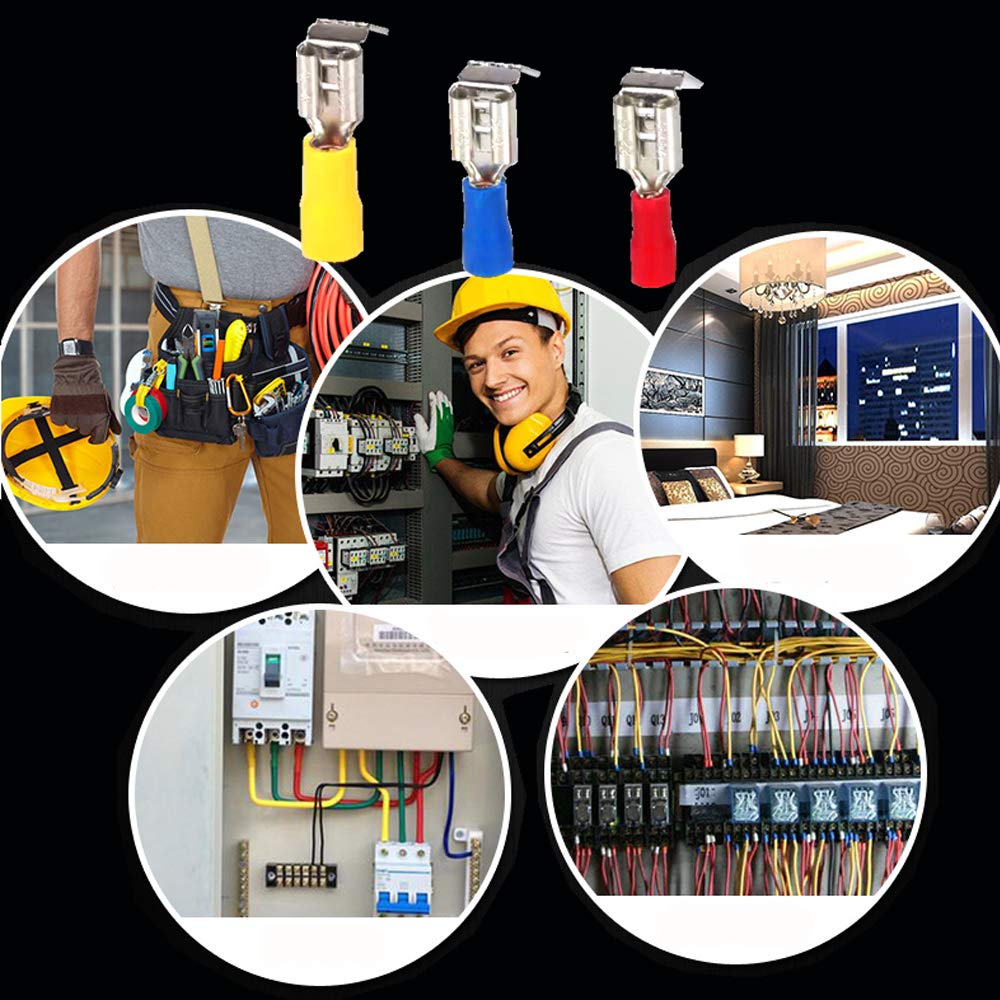
| Wire Size (AWG) | Terminal Color Code | Max Current Rating | Typical Applications |
|---|---|---|---|
| 22-18 AWG | Red | 15 Amperes | Control circuits, instrumentation |
| 16-14 AWG | Blue | 25 Amperes | Lighting circuits, small motors |
| 12-10 AWG | Yellow | 35 Amperes | Power circuits, large motors |
Environmental Rating Selection
Temperature Ratings:
- Standard Grade: -40°F to +221°F (-40°C to +105°C)
- High Temperature: -40°F to +347°F (-40°C to +175°C)
- Marine Grade: Tin-plated copper for corrosion resistance
Insulation Materials:
- Nylon: Standard applications, good chemical resistance
- Heat Shrink: Enhanced moisture protection
- Vinyl: Economy applications, limited temperature range
Expert Tips for Professional Installation
💡 Professional Best Practices
- Terminal Inspection: Always inspect terminals for cracks or damage before installation
- Wire Preparation: Use quality wire strippers to prevent conductor damage
- Crimp Quality: Properly crimped terminals show slight wire deformation through insulation
- Environmental Protection: Apply dielectric grease in corrosive environments
- Load Calculation: Verify total circuit load doesn’t exceed terminal current rating
Common Installation Mistakes to Avoid
- Over-crimping: Can damage conductors and reduce current capacity
- Under-crimping: Creates high-resistance connections and potential failure
- Wrong Size Selection: Mismatched terminals compromise connection integrity
- Inadequate Insulation: Can create short circuits in tight installations
- Mixing Terminal Types: Different manufacturers may have compatibility issues
Troubleshooting Common Problems
Problem: Intermittent Connection
Cause: Poor crimp quality or terminal corrosion
Solution: Re-crimp with proper tool or replace terminals
Problem: Overheating at Connection Point
Cause: Undersized terminal or excessive current draw
Solution: Verify load calculations and upgrade terminal size if necessary
Problem: Terminal Separation Under Vibration
Cause: Inadequate mechanical connection or worn terminals
Solution: Replace terminals and verify positive engagement
When to Consult a Professional Electrician
⚠️ Professional Installation Required For:
- High-voltage applications (over 120V)
- Permanent building wiring modifications
- Code compliance inspections
- Industrial control systems
- Marine electrical installations requiring ABYC compliance
Quick Reference: Terminal Selection Guide
Automotive Applications
- Use 16-14 AWG terminals for standard automotive circuits
- Select marine-grade terminals for under-hood applications
- Verify SAE J1128 wire compatibility
Industrial Applications
- Choose UL Listed terminals for NEC compliance
- Use temperature ratings appropriate for panel environment
- Consider vibration-resistant designs for motor applications
Marine Applications
- Select tin-plated terminals for corrosion resistance
- Use heat-shrink insulation for moisture protection
- Verify ABYC E-11 compliance for safety systems
Frequently Asked Questions
Q: Can piggyback terminals be used in permanent building wiring?
A: Yes, when properly installed and code-compliant. They must be accessible for inspection and maintenance per NEC requirements.
Q: What’s the maximum current rating for piggyback terminals?
A: Current rating depends on wire gauge and terminal design. Standard terminals range from 15-35 amperes for 22-10 AWG wire sizes.
Q: Are piggyback terminals waterproof?
A: Standard terminals are not waterproof. Marine-grade terminals with heat-shrink insulation provide moisture resistance but require proper installation.
Q: Can multiple piggyback terminals be stacked?
A: While physically possible, stacking creates reliability concerns. Consult manufacturer specifications and consider alternative connection methods for multiple circuits.
Q: How do I verify proper crimp quality?
A: A properly crimped terminal shows slight wire deformation through the insulation and passes a gentle pull test without wire movement.
Q: What tools are required for professional installation?
A: Calibrated crimping tool, wire strippers, multimeter for testing, and appropriate safety equipment including lockout/tagout devices.
Q: Are piggyback terminals code-compliant for residential use?
A: When properly installed using UL Listed components, piggyback terminals meet NEC requirements for residential applications.
Q: How long do piggyback terminals last?
A: When properly installed and maintained, quality terminals can provide 20+ years of reliable service in appropriate environments.
Professional Recommendation
For critical applications requiring absolute reliability, consult with a licensed electrician to ensure proper installation, code compliance, and system safety. Piggyback terminals provide excellent connectivity solutions when properly applied within their design parameters and environmental limitations.
Need Expert Installation? Contact a licensed electrician certified in your application area for professional installation and inspection services.
