
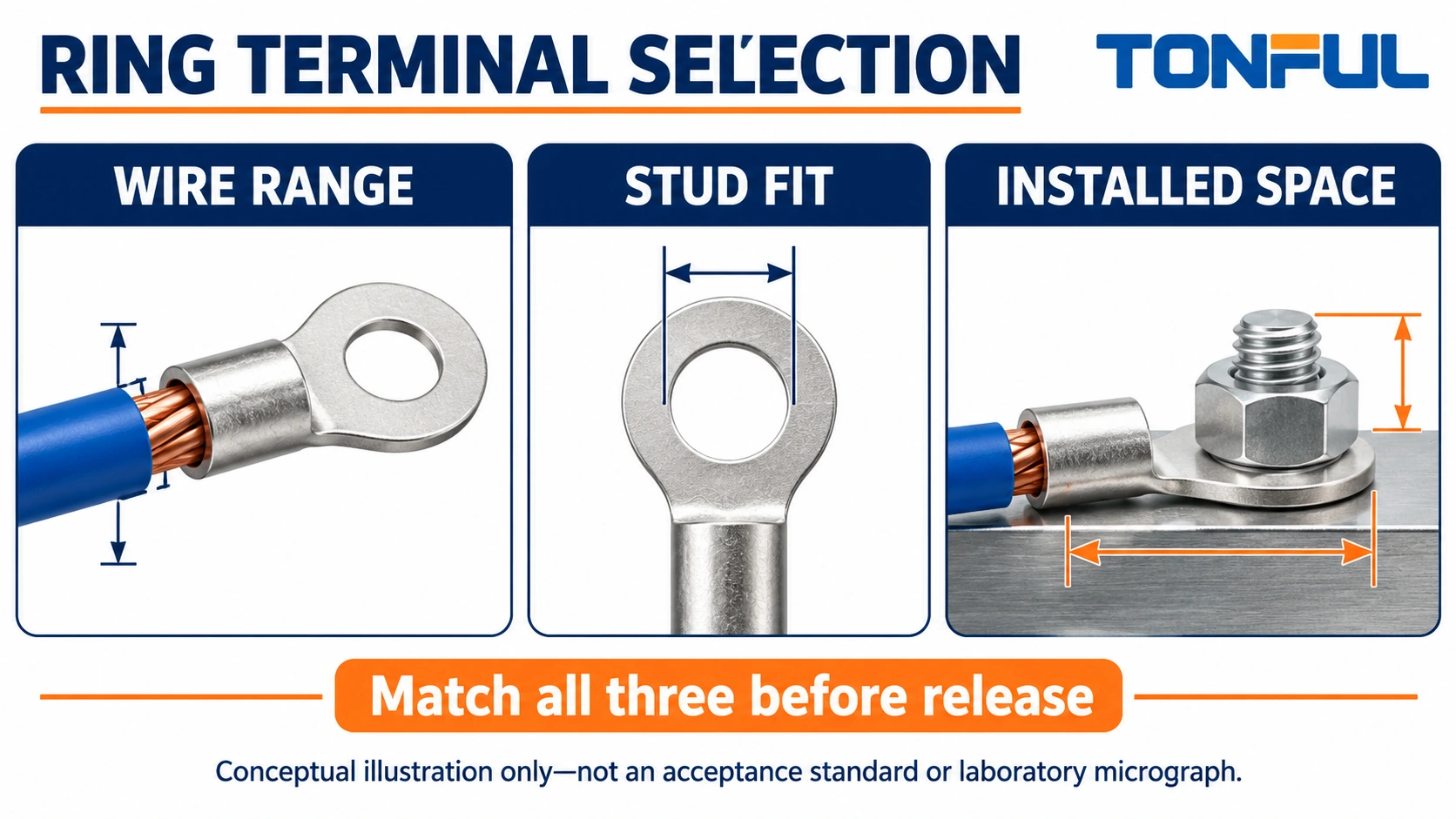
Ring terminal selection requires three independent matches: the barrel to the conductor, the eye to the stud arrangement, and the complete termination to the available space. A terminal can pass one check and fail the others. A correct wire-range marking does not prove that the tongue fits the equipment or that the wire can leave the barrel without interference.
A ring terminal has a closed eye that surrounds a stud or screw. Installing or removing it generally requires opening the fastener arrangement sufficiently to pass the eye over the fastener. That retention geometry does not remove the need for correct clamping, routing or inspection. Use the following review to turn a catalog candidate into a documented assembly choice.
Jump to: Selection inputs | Conductor | Stud fit | Space | Release | Inquiry
Ring Terminal Selection Starts With Three Interfaces
Separate component identity from suitability
Start with a drawing or controlled specification, not a photograph of a similar terminal. Record the terminal part number, drawing revision, wire range and eye designation. Then identify the actual equipment terminal and permitted attachment method. A nominal stud label alone does not describe the contact surface, barriers, hardware stack or allowed terminal styles.
As a terminology reference, TE Connectivity’s ring and spade overview distinguishes the closed ring from the open spade form. The practical consequence is access: the eye must pass over the fastener arrangement, whereas an approved fork can approach an exposed clamping location laterally. Equipment instructions still govern which form is allowed.
| Interface | Inputs to collect | Question before release |
|---|---|---|
| Wire to barrel | Wire part number, conductor construction, material and jacket diameter | Is this exact wire covered by the terminal instruction? |
| Eye to equipment | Stud details, contact pad, hardware and terminal restrictions | Can the tongue seat as intended without modification? |
| Assembly to enclosure | Barriers, cover, wire exit and tool approach | Can it be installed and serviced without interference? |
Screen the application before choosing a part
Record circuit function, operating conditions and access restrictions. Do not derive a current rating solely from wire size or the apparent thickness of the ring. The equipment connection, terminal, conductor and surrounding thermal conditions all affect the design. Obtain the applicable part information and system requirements rather than assigning a universal limit.
TONFUL’s wire-terminal manufacturing page provides a starting point for candidate sourcing. Treat product-family descriptions as a way to identify relevant parts, not as evidence that every ring terminal has identical material, approval or environmental capability. Put those requirements in the inquiry so they can be checked against the specific candidate.
Match the Barrel to the Conductor
Confirm more than nominal cross-section
Record AWG or metric conductor area as specified by the wire document, without treating approximate conversions as exact equivalence. Also record strand construction, conductor material and any coating. A barrel designed for one conductor construction is not automatically approved for a different strand class or a different metal simply because the nominal area is similar.
The sleeve opening and any insulation support must accommodate the jacket diameter. A wire can have an acceptable conductor area but an unsuitable insulation diameter. Inspect the wire document and the terminal instruction together. Do not cut strands, remove extra insulation indiscriminately or force the conductor into the barrel to make a stock part fit.
Choose the insulation arrangement deliberately
For pre-insulated candidates, compare TONFUL’s nylon-insulated terminals. Confirm which surfaces the sleeve covers and whether it includes a separate support feature. A barrel sleeve does not necessarily cover the ring tongue, stud or completed hardware. It should not be described as making the assembly touch-safe or waterproof without supporting evidence.
Where the equipment or assembly provides a different protection method, review non-insulated terminal constructions. Include the complete protection arrangement in the assembly drawing. Removing insulation from a purchased terminal is not a controlled substitute for selecting an approved bare-terminal part.
Lock the crimp system before ordering production stock
Identify the tool, die or cavity, locator where applicable and required terminal orientation. A ring tongue shape does not determine the crimp cavity. Different barrel constructions can need different tooling even when their stud holes match. Ask for the instruction linking the terminal to the intended wire and tool.
For trial samples, record strip length and conductor insertion against the part instruction. Check for missing strands, jacket trapped in the conductor crimp and damage caused by stripping. The acceptance limits belong to the approved system documentation. A firm hand tug or a visually symmetrical barrel is not enough to establish a qualified production process.
Review the Stud and Tongue Interface
Use the actual eye dimensions
Check the drawing’s hole diameter and tolerances against the actual stud or screw arrangement. Nominal naming systems are useful for ordering, but the dimensional documents resolve fit. Avoid enlarging the hole, filing the tongue or bending it to clear neighboring hardware; those changes alter the supplied component and require an approved engineering disposition.
Review tongue width, thickness, overall length and the transition between tongue and barrel. The tongue must seat on the intended contact surface without riding on a shoulder, recess or barrier. A hole that passes over the stud is only the first fit check. The remaining metal must be supported and clamped in the intended arrangement.

Follow the equipment hardware instructions
Use the specified fasteners, washers, stacking order and tightening method. Do not prescribe one universal washer stack or torque for every ring terminal. The equipment manufacturer’s permitted arrangement matters, including whether multiple terminals may share a stud. Terminal thickness and stack height can affect available thread engagement and cover clearance.
If more than one ring is proposed, request explicit approval of the stack and wire routing. Do not assume the eye geometry authorizes unlimited stacking. Consider whether tightening the fastener rotates a tongue or loads another wire. Restrain the assembly as directed without using the conductor as a lever or bending the barrel after crimping.
When reviewing a sample, identify the datum surfaces used for each measurement. Record eye diameter separately from tongue width, and distinguish overall terminal length from the distance that controls a nearby barrier. A photograph with a ruler can explain the layout but should not replace the controlled drawing or a suitable dimensional inspection. Where supplier drawings use different dimension names, annotate the interface review so both teams compare the same feature.
Distinguish capture from electrical contact
A closed eye can remain around a loosened stud while the electrical interface becomes unacceptable. Therefore, ring geometry should not be marketed as preventing every loose connection. The clamped contact still needs the correct hardware, preparation and installation process. Any anti-rotation feature must be identified on the actual part or equipment drawing rather than inferred from a photograph.
Check Installation and Service Space
Measure the finished envelope
Include sleeve outside diameter, barrel length, tongue width, wire exit and installed protection. Check these against pole barriers, nearby conductors and the cover. A ring selected on a bare equipment drawing can collide with a barrier once the actual sleeve and wire are added. Use a representative sample when drawings leave the transition geometry unclear.
Allow the wire to leave the barrel along an approved route without being pulled sideways by a tight bend or cable restraint. Review routing with the cover closed and the harness supported. Do not establish a generic bend radius in a terminal guide; obtain the wire and equipment requirements for the actual construction and use conditions.
Reserve room for tools and maintenance
Confirm access for the required fastener tool and for any tool needed to hold the assembly in position. Also consider how the ring will be removed later. A terminal that can be assembled before a neighboring component is fitted may become inaccessible during service. Document the intended sequence instead of assuming the initial installation proves maintainability.
Work only under an approved safe-isolation procedure with qualified personnel, control of stored energy and verification of the deenergized state. Never loosen a ring terminal to investigate an energized connection. Safety-critical circuits, including vehicle restraint and traction systems, require the applicable equipment-specific service instructions and approved repair methods, not a generic terminal substitution.
Document the Selection and Verification
Use a release table with evidence references
The following record is a review template, not a test report. Enter the actual document reference, reviewer and result for each row. An unresolved interface is a hold point rather than an invitation to select the closest available item.
| Review item | Evidence or record | Hold condition |
|---|---|---|
| Conductor compatibility | Wire document and terminal application instruction | Wire construction not covered |
| Eye fit | Terminal and equipment dimensions | Required fit cannot be confirmed |
| Tongue support | Contact-surface drawing or reviewed sample | Tongue rests on a barrier or shoulder |
| Hardware | Equipment attachment instruction | Stack or torque source missing |
| Tooling | Tool and cavity compatibility instruction | Only generic tool range available |
| Envelope | Installed assembly drawing or trial record | Sleeve, wire or cover interference |
| Protection | Guarding and insulation plan | Accessible metal not addressed |
| Authorization | Engineering approval and revision | Open deviation or substitution |

Verify the process without inventing limits
Trial the approved wire-terminal-tool combination using representative material. Define visual checks and any required dimensional, mechanical or electrical verification under the applicable qualification plan. Keep sample identity and tooling records. TONFUL’s crimp-quality validation guide provides related process context, but does not replace your part-specific acceptance source. Do not replace that plan with a universal pull-force number taken from another terminal family or an informal comparison between different wire constructions.
Production controls should identify when first-piece review repeats, such as an approved tool change or a new wire construction. Purchasing substitutions need the same interface review, not merely a matching wire-range color. Where a new supplier proposes equivalent geometry, request the drawing, instructions and qualification evidence before considering the part interchangeable.
Prepare a Useful TONFUL Inquiry
Send the interface package rather than a single size
Include wire part number and construction, equipment connection details, eye dimensions, tongue envelope, insulation preference and available installation space. Add the required tooling approach and any customer-specific approval requirements. Photographs can explain access constraints, but pair them with dimensions and document revisions so the supplier is not asked to estimate fit from perspective.
Use TONFUL’s crimping-tool range to discuss the intended assembly process alongside the terminal request. Ask for a candidate ring terminal, matching tooling information and the evidence needed for your release review. Confirm the installed sample before approving production supply; the correct choice is the documented combination that fits the wire, stud and space together.