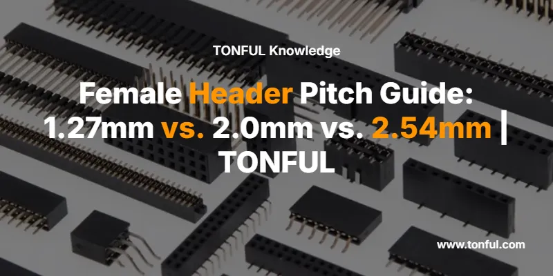
By TONFUL Electric | PCB Connector Engineering Series
When selecting a female header or pin header connector for your PCB design, one specification dominates every other consideration: pitch — the center-to-center distance between adjacent pins. Choose the wrong pitch and your connector simply won’t mate. Choose it wisely, and you unlock the perfect balance of board density, current capacity, and manufacturing efficiency. This guide breaks down the three most prevalent pitches in modern electronics — 1.27mm, 2.0mm, and 2.54mm — with the technical depth B2B engineers and procurement teams need.

What Is Connector Pitch?
Pitch is the uniform distance, measured in millimeters, from the center of one pin to the center of the adjacent pin. It is the single most critical dimensional parameter when mating a female header to a male pin header, a PCB footprint, or a ribbon cable IDC connector. A 0.1mm mismatch renders two connectors completely incompatible — there is no workaround short of a custom adapter.
The three pitches covered here — 1.27mm (0.050″), 2.0mm (0.079″), and 2.54mm (0.100″) — represent the dominant range for signal and low-power applications across industrial, automotive, consumer, and IoT electronics. Each has a distinct engineering rationale, and understanding those rationales is the foundation of sound connector selection.
For a broader look at how TONFUL’s PCB connector portfolio is organized, see our full product range including box header connectors and wafer connectors.

Core Specifications at a Glance
| Parameter | 1.27mm Pitch | 2.0mm Pitch | 2.54mm Pitch |
|---|---|---|---|
| Inch Equivalent | 0.050″ | 0.079″ | 0.100″ |
| Also Known As | Half-pitch, 0.050″ | 2mm pitch | Standard pitch, 0.1″ |
| Pin Size (Typical) | 0.50mm round/square | 0.50mm square | 0.64mm square |
| Typical Current Rating | 1.0 A per pin | 1.5 A per pin | 3.0 A per pin |
| Dielectric Withstand | AC 500V | AC 500V | AC 550V |
| Operating Temp | -55°C to +105°C | -55°C to +105°C | -55°C to +105°C |
| Housing Material | PA6T / PBT (UL94V-0) | PA6T / PBT | Nylon 6T / PBT |
| Contact Material | Phosphor bronze / brass | Phosphor bronze / brass | Phosphor bronze / brass |
| Plating | Gold (0.3–3μm) / Tin | Gold / Tin | Gold / Tin |
| Mount Type | THT / SMT | THT / SMT | THT / SMT |
| Pins per Row (typical) | 2–50 | 2–40 | 2–40 |
| Impedance | ~100 Ω | 85–100 Ω | ~100 Ω |
| Mating Cycles | 30–50 (standard) | 50–100 | 100–500+ |
| RoHS / REACH | ✅ | ✅ | ✅ |
Deep Dive: 2.54mm Pitch Female Header — The Universal Standard
The 2.54mm (0.100″) pitch female header is the most widely deployed connector pitch in the history of PCB design. Its origin traces back to the era of DIP ICs and ribbon cable systems, where 0.1″ spacing became the de facto standard — a legacy that persists today in Arduino shields, breadboard systems, development boards, and legacy industrial controllers.
Why Engineers Still Choose 2.54mm
The 2.54mm pitch’s enduring dominance comes down to three factors: current capacity, hand-soldering ease, and ecosystem breadth. At 3A per pin (with appropriate wire gauge), it handles a wider range of power loads than finer pitches. Its 0.64mm square pins are large enough for reliable hand-soldering in prototyping and low-volume production. And the sheer number of compatible mating connectors, IDC cables, and PCB footprint libraries available makes it the path of least resistance for most non-space-constrained designs.
TONFUL’s female header connectors in 2.54mm pitch are available in single-row and dual-row configurations, straight and right-angle orientations, with gold or tin plating options. They are fully compatible with standard 0.1″ breadboards and Arduino-family development boards.
Typical Applications: Arduino/Raspberry Pi shields, industrial PLCs, legacy telecom equipment, test & measurement jigs, power distribution boards, educational electronics.
Deep Dive: 2.0mm Pitch Female Header — The Industrial Middle Ground
The 2.0mm pitch occupies a strategically important position between the ubiquitous 2.54mm standard and the high-density 1.27mm format. It delivers a 22% reduction in board footprint compared to 2.54mm while maintaining a current rating of approximately 1.5A per pin — sufficient for the vast majority of signal and low-power applications.
The 2.0mm Advantage in Industrial IoT
This pitch has become the connector of choice for industrial IoT gateways, network switches, embedded computing modules, and XBee wireless platforms. Its 0.50mm square pins are robust enough to withstand moderate vibration environments, and its slightly tighter spacing allows designers to increase pin density without committing to the manufacturing precision demands of 1.27mm SMT assembly.
The 2.0mm pitch female header is particularly well-suited to wire-to-board applications where a cable harness must connect to a PCB in a space-constrained enclosure. Its Y-type contact geometry in many TONFUL variants provides a vibration-resistant connection that exceeds the mechanical retention of standard 2.54mm designs.
Typical Applications: IoT sensor nodes, industrial computers, network switches, XBee/Zigbee modules, medical monitoring devices, automotive body control modules.
Deep Dive: 1.27mm Pitch Female Header — High-Density Precision
The 1.27mm (0.050″) pitch — often called “half-pitch” because it is exactly half of the 2.54mm standard — represents the frontier of mainstream PCB connector miniaturization. Packing pins at half the spacing of the 0.1″ standard, a dual-row 1.27mm female header can deliver 60+ signal channels in the same PCB area that a 2.54mm connector uses for 20.
Engineering Realities of 1.27mm
The density gains come with important trade-offs. At 1.0A per pin, the 1.27mm pitch is strictly a signal and low-power connector — it is not appropriate for power distribution. Its fine pin geometry demands automated SMT placement for reliable production; hand-soldering at 1.27mm pitch is technically possible but introduces unacceptable defect rates in volume manufacturing. Keyed and shrouded housing designs are strongly recommended to prevent mis-mating, which is a genuine risk when pins are this closely spaced.
The 1.27mm female header excels in board-to-board stacking architectures — mezzanine configurations common in 5G base stations, high-density servers, JTAG/JTAG-ETM debug interfaces, and compact embedded systems where every square millimeter of PCB area carries a cost premium.
Typical Applications: Server mezzanine boards, 5G base station modules, JTAG debug headers, compact SBCs, medical implantable devices, aerospace avionics, high-speed data acquisition systems.

Side-by-Side Comparison: Which Pitch Is Right for Your Design?
| Design Requirement | Best Pitch Choice | Reason |
|---|---|---|
| Arduino / breadboard prototyping | 2.54mm | Universal compatibility, hand-solderable |
| High board density, signal-only | 1.27mm | 50% space saving vs. 2.54mm |
| Industrial IoT / embedded modules | 2.0mm | Balance of density and current capacity |
| Power distribution (>2A per pin) | 2.54mm | Higher current rating per contact |
| Automated SMT production | 1.27mm or 2.0mm | Finer pitch suits pick-and-place |
| Vibration-heavy environments | 2.0mm or 2.54mm | Larger pins, higher retention force |
| JTAG / debug interfaces | 1.27mm | Industry-standard for ARM debug headers |
| Legacy system compatibility | 2.54mm | Widest ecosystem of mating connectors |
| Space-constrained wearables / IoT | 1.27mm | Maximum pin density per mm² |
| Wire-to-board harness connections | 2.0mm | Good balance of density and robustness |
Pitch and Signal Integrity: What Engineers Often Overlook
Beyond mechanical fit and current capacity, pitch has a measurable impact on signal integrity at higher frequencies. Tighter pin spacing increases capacitive coupling between adjacent contacts, which can degrade signal quality in high-speed differential pairs above ~100MHz. For most industrial and IoT applications operating below this threshold, the effect is negligible. However, for JTAG trace capture (up to 150MHz per Segger specifications), 1.27mm IDC connectors are explicitly rated and recommended — a testament to how well-engineered fine-pitch connectors can perform when properly specified.
The impedance of all three pitches falls in the 85–100Ω range for standard configurations, making them compatible with common differential signaling standards (LVDS, RS-422) when used with matched cable assemblies.

Material & Plating: What’s Inside a TONFUL Female Header
The performance of any female header connector is ultimately determined by the quality of its two core materials: the insulator housing and the contact metal.
| Component | Material Options | TONFUL Standard |
|---|---|---|
| Insulator Housing | Nylon 6T, PA6T, PBT, LCP | PA6T (UL94V-0, 280°C reflow rated) |
| Contact Base Metal | Brass, Phosphor Bronze, Beryllium Copper | Phosphor Bronze (C5191) |
| Contact Plating | Tin (Sn), Gold (Au 0.3–3μm), Nickel undercoat | Selective gold / full tin options |
| Solder Tail Plating | Tin-Lead (legacy), Lead-Free Sn | RoHS-compliant Lead-Free Sn |
Phosphor bronze contacts offer superior spring-back characteristics over brass, maintaining consistent contact force across the rated mating cycles. Gold plating (even at 0.3μm flash) dramatically reduces contact resistance and prevents oxidation in humid or corrosive environments — a critical consideration for automotive electrical connectors and marine-grade PCB assemblies.
Mounting Configurations Compared
| Configuration | 1.27mm | 2.0mm | 2.54mm | Best Use Case |
|---|---|---|---|---|
| Straight THT | ✅ | ✅ | ✅ | General PCB mounting |
| Right-Angle THT | ✅ | ✅ | ✅ | Panel-edge connectors |
| SMT (Surface Mount) | ✅ | ✅ | ✅ | High-volume automated assembly |
| Single Row | ✅ | ✅ | ✅ | Simple signal routing |
| Dual Row | ✅ | ✅ | ✅ | High pin count, compact footprint |
| Shrouded / Keyed | ✅ | ✅ | ✅ | Mis-mating prevention |
| Low-Profile | ✅ | ✅ | Limited | Stacked board designs |

TONFUL’s PCB Connector Product Range
TONFUL Electric manufactures a comprehensive range of PCB interconnect solutions beyond female headers. Our pin header connectors cover all three pitch sizes in both THT and SMT variants. Our box header connectors provide shrouded, keyed mating for ribbon cable applications. For board-to-board signal routing in dense assemblies, our wafer connectors and FPC/FFC connectors extend the portfolio into sub-1mm pitch territory.
For engineers sourcing complete connector kits, our assorted boxes include mixed-pitch header and socket combinations ideal for prototyping labs and field service teams. Our terminals and connectors manufacturing capabilities support custom pitch, custom pin count, and private-label OEM programs.
Quick Selection Decision Tree
Is board space a primary constraint?
├── YES → Is current per pin > 2A?
│         ├── YES → Use 2.54mm (higher current capacity)
│         └── NO  → Use 1.27mm (maximum density)
└── NO  → Is hand-soldering required in production?
          ├── YES → Use 2.54mm (easiest to hand-solder)
          └── NO  → Is this an industrial/IoT module?
                    ├── YES → Use 2.0mm (best balance)
                    └── NO  → Use 2.54mm (widest ecosystem)
Frequently Asked Questions (FAQ)
Q1: Can I use a 2.54mm female header with a 2.0mm male pin header?
No. Pitch mismatch means the pins will not align with the socket contacts. Even a 0.54mm difference causes physical interference or complete non-contact. Always confirm pitch before ordering mating pairs.
Q2: What does “dual-row” mean for a female header connector?
A dual-row female header has two parallel rows of socket contacts. For example, a 2×10 dual-row 2.54mm header has 20 contacts total, arranged in two rows of 10, with 2.54mm spacing between pins in each row and typically 2.54mm between the two rows as well.
Q3: Is 1.27mm pitch suitable for power connections?
Generally no. With a typical rating of 1.0A per pin, 1.27mm pitch connectors are designed for signal and low-power data lines. For power distribution above 1A per pin, 2.0mm or 2.54mm pitch is the appropriate choice.
Q4: What is the difference between THT and SMT female headers?
Through-hole technology (THT) headers have pins that pass through drilled PCB holes and are soldered on the underside — robust and suitable for hand-soldering. Surface-mount technology (SMT) headers have bent solder tails that sit on PCB pads and are reflowed — preferred for automated high-volume production and lower-profile assemblies.
Q5: How do I identify the pitch of an unknown female header connector?
Measure the distance between the centers of the first and last pin in a row, then divide by (number of pins − 1). For example, a 10-pin row measuring 22.86mm gives 22.86 ÷ 9 = 2.54mm pitch. A digital caliper accurate to 0.01mm is sufficient for this measurement.
Q6: Does TONFUL offer custom pitch or custom pin count female headers?
Yes. TONFUL Electric supports OEM and ODM programs for custom connector configurations. Contact our engineering team via tonful.com to discuss custom pitch, pin count, housing color, plating specification, and private labeling requirements.
Q7: What certifications do TONFUL PCB connectors carry?
TONFUL’s PCB connector range is manufactured under ISO 9001 quality management systems and products carry RoHS and REACH compliance. Housing materials meet UL94V-0 flame retardancy standards.
Conclusion
Selecting the right connector pitch is not a minor detail — it is a foundational engineering decision that affects board density, assembly process, current capacity, and long-term reliability. The 2.54mm female header remains the gold standard for prototyping, legacy compatibility, and power-adjacent applications. The 2.0mm pitch delivers an intelligent compromise for industrial IoT and embedded modules where space matters but robustness cannot be sacrificed. The 1.27mm pitch is the engineer’s choice when maximum pin density and SMT automation are the primary drivers.
TONFUL Electric supplies all three pitch families with consistent material quality, RoHS-compliant plating, and the manufacturing scale to support both prototype quantities and high-volume OEM programs. Explore our full PCB connector range or contact our technical sales team to specify the right female header for your next design.
TONFUL Electric — Professional B2B Manufacturer of Electrical Connectors, Terminals & PCB Interconnects
tonful.com | terminals-connectors-manufacturer | auto-connector-manufacturer
