
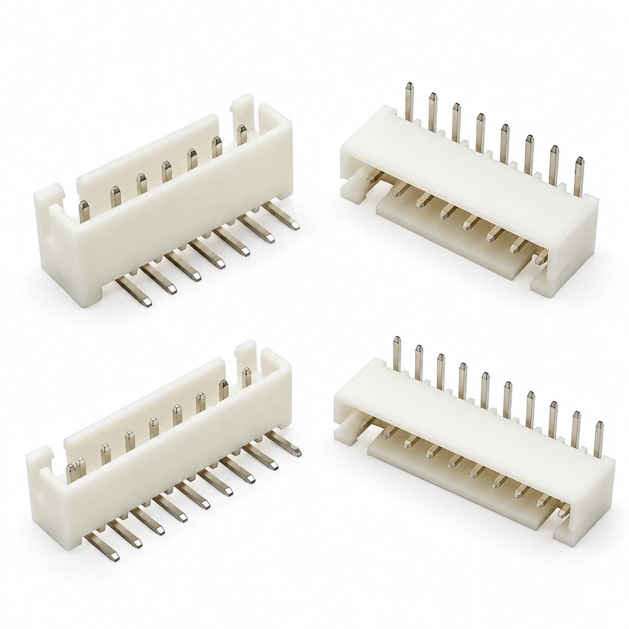
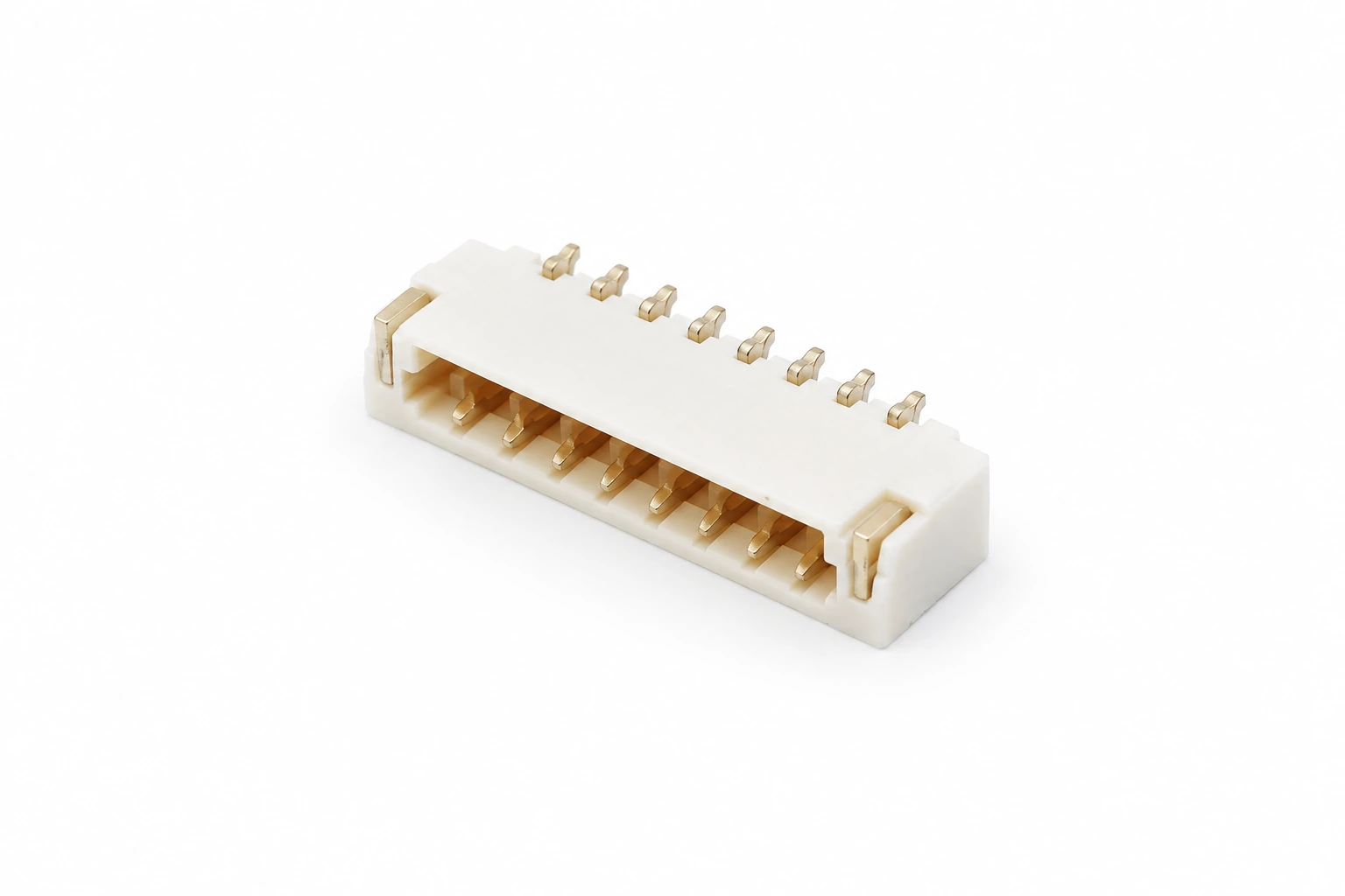
Wafer Connector Manufacturer for OEM & Wholesale

Source wire-to-board wafer connectors from TONFUL Electric for compact electronics, appliance controls and industrial assemblies. Compare eight catalog configurations, then share your pitch, circuit count, PCB footprint, mating housing and order quantity.

Wafer connector selection — illustrative image

Wafer Connector Product Range

Explore eight catalog configurations covering different pitches and SMT or through-hole mounting styles. Use the examples to begin selection, then confirm the drawing, circuit count and complete mating assembly with TONFUL.

0.8 mm 8-Pin Wafer Connector — illustrative product image

0.8 mm 8-Pin Wafer Connector

0.8 mm 8-Pin Wafer Connector. Confirm circuit count, PCB footprint, mating housing and terminal details against the approved model drawing.
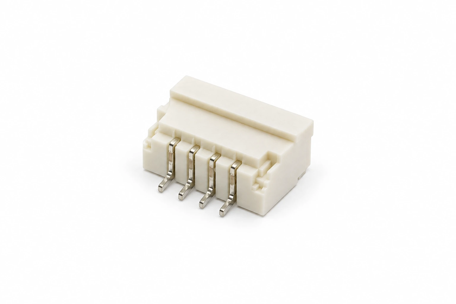
1.0 mm Right-Angle SMT Wafer Connector — illustrative product image

1.0 mm Right-Angle SMT Wafer Connector

1.0 mm Right-Angle SMT Wafer Connector. Confirm circuit count, PCB footprint, mating housing and terminal details against the approved model drawing.
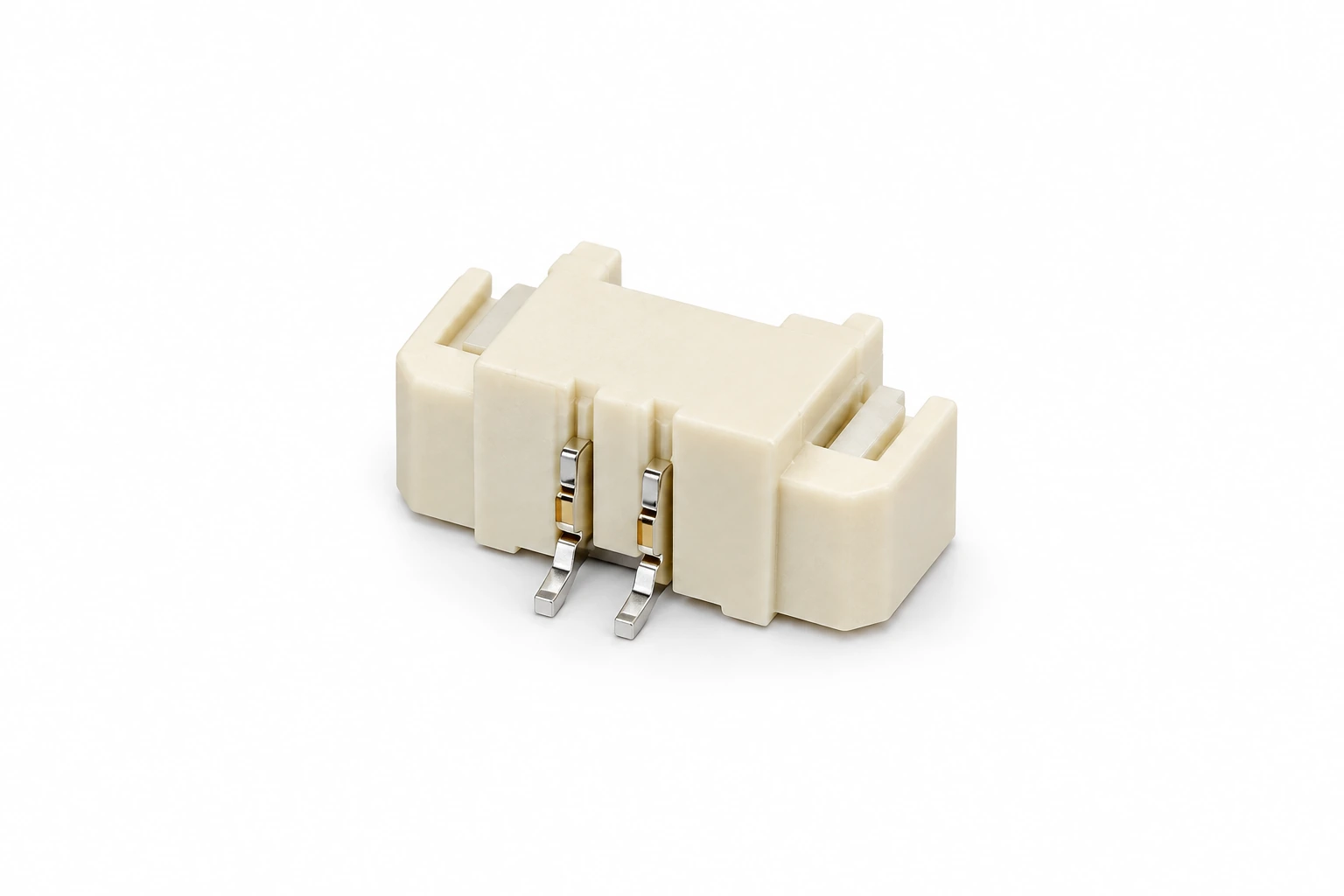
1.25 mm SMT Wafer Connector — illustrative product image

1.25 mm SMT Wafer Connector

1.25 mm SMT Wafer Connector. Confirm circuit count, PCB footprint, mating housing and terminal details against the approved model drawing.
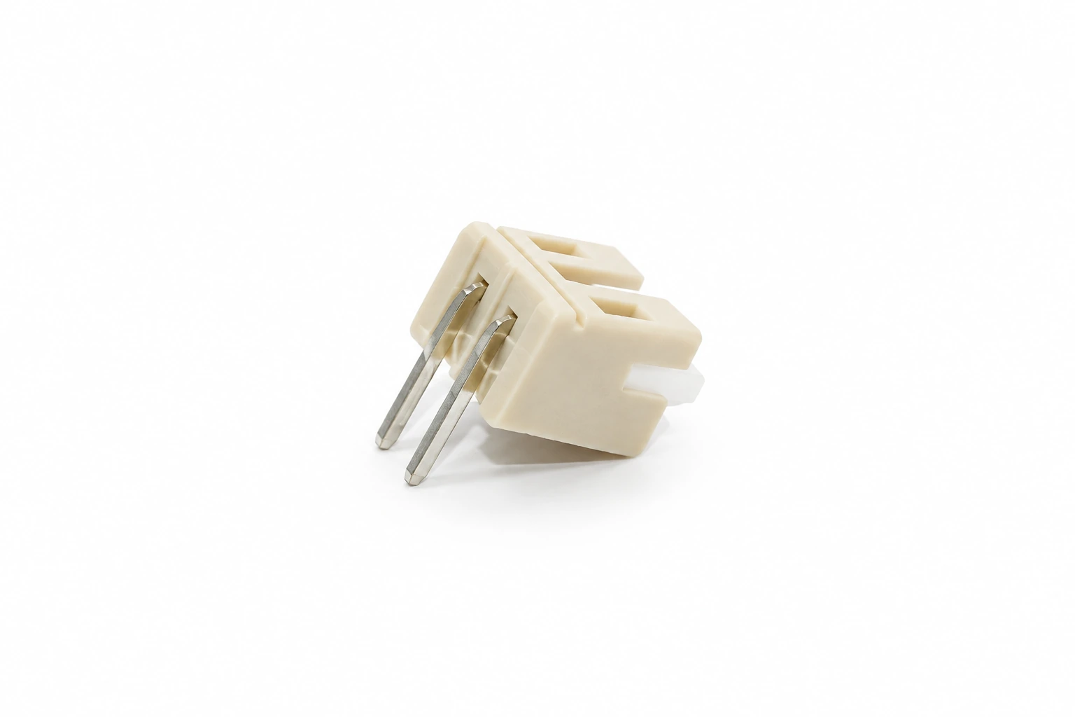
2.0 mm Right-Angle Through-Hole Wafer Connector — illustrative product image

2.0 mm Right-Angle Through-Hole Wafer Connector

2.0 mm Right-Angle Through-Hole Wafer Connector. Confirm circuit count, PCB footprint, mating housing and terminal details against the approved model drawing.
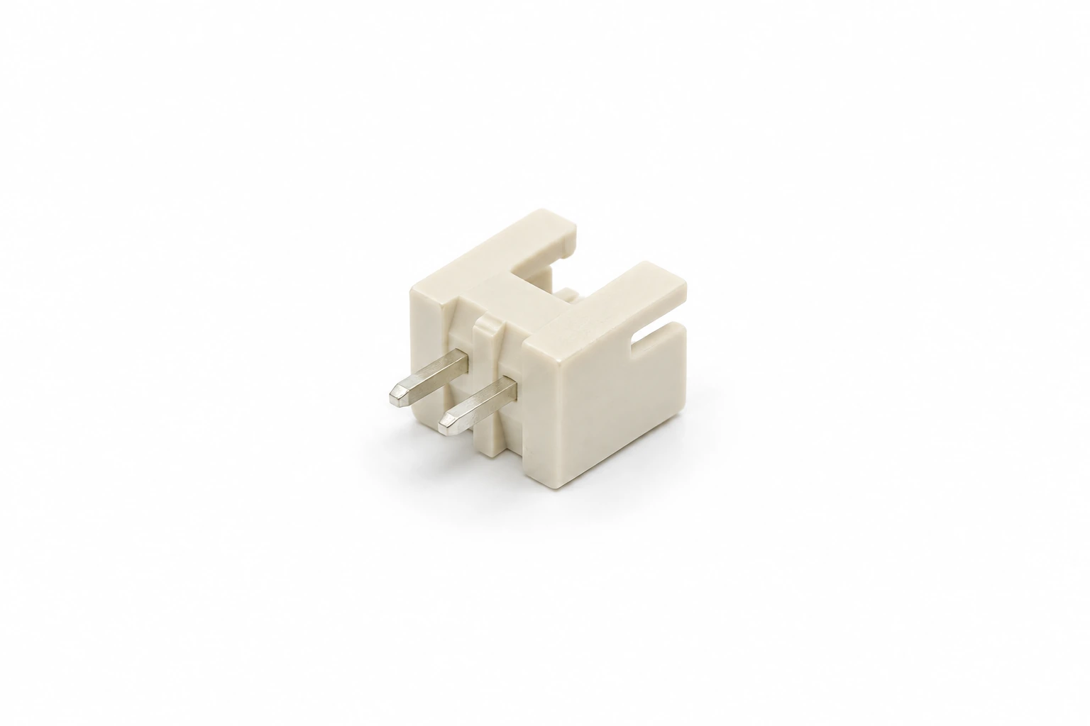
2.5 mm Through-Hole Wafer Connector — illustrative product image

2.5 mm Through-Hole Wafer Connector

2.5 mm Through-Hole Wafer Connector. Confirm circuit count, PCB footprint, mating housing and terminal details against the approved model drawing.
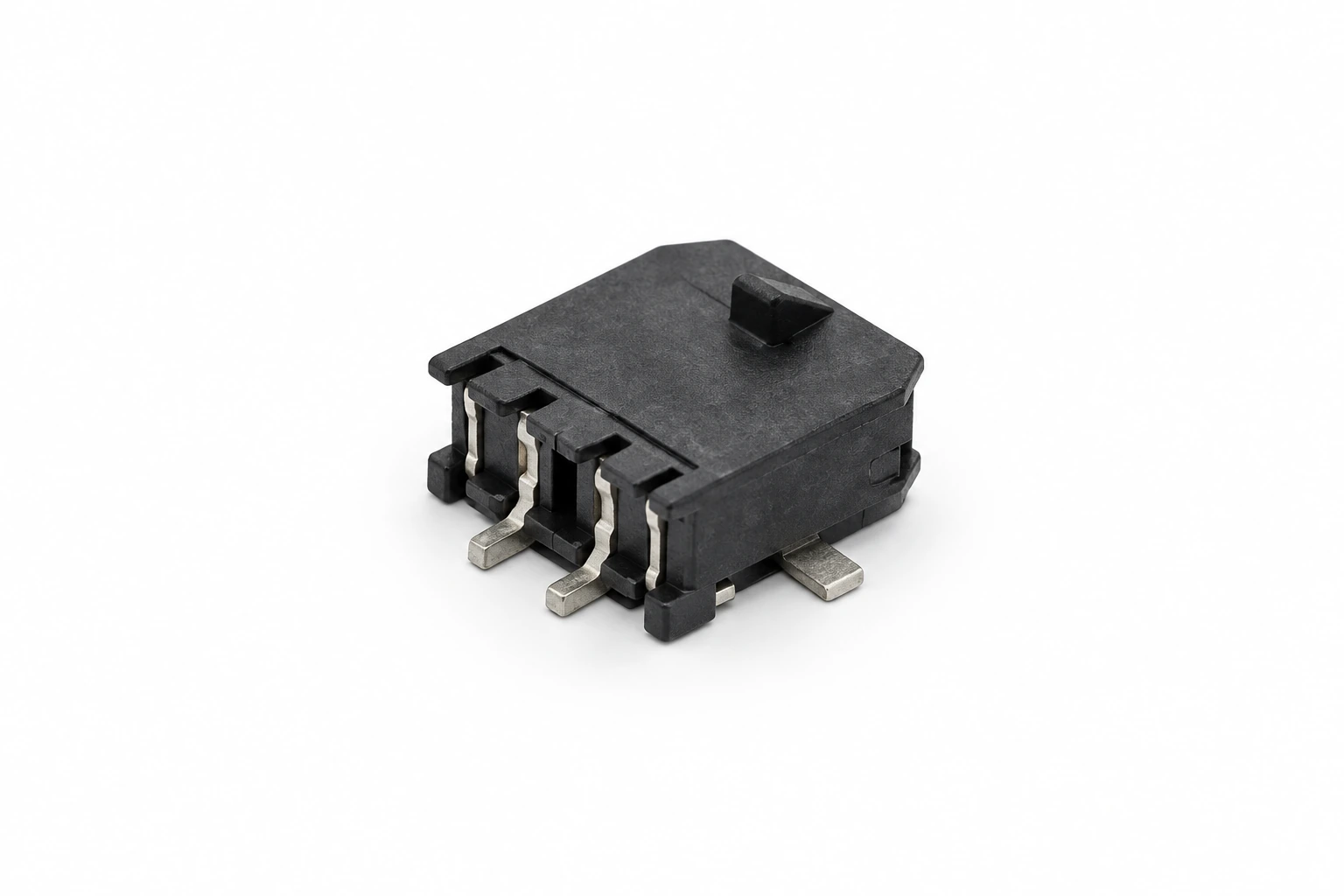
3.0 mm SMT Wafer Connector — illustrative product image

3.0 mm SMT Wafer Connector

3.0 mm SMT Wafer Connector. Confirm circuit count, PCB footprint, mating housing and terminal details against the approved model drawing.
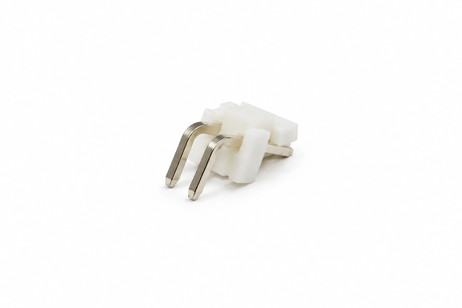
3.96 mm Right-Angle Through-Hole Wafer Connector — illustrative product image

3.96 mm Right-Angle Through-Hole Wafer Connector

3.96 mm Right-Angle Through-Hole Wafer Connector. Confirm circuit count, PCB footprint, mating housing and terminal details against the approved model drawing.
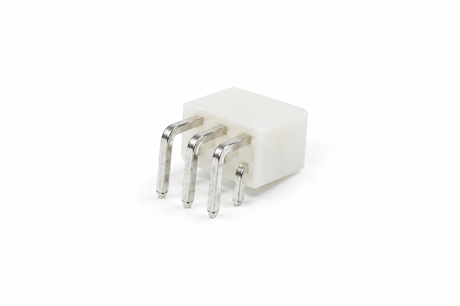
4.2 mm Right-Angle Through-Hole Wafer Connector — illustrative product image

4.2 mm Right-Angle Through-Hole Wafer Connector

4.2 mm Right-Angle Through-Hole Wafer Connector. Confirm circuit count, PCB footprint, mating housing and terminal details against the approved model drawing.
Product images illustrate catalog configurations. The approved drawing and sample define pitch, pin count, mounting details and the supplied mating components.

Wafer Connector Applications

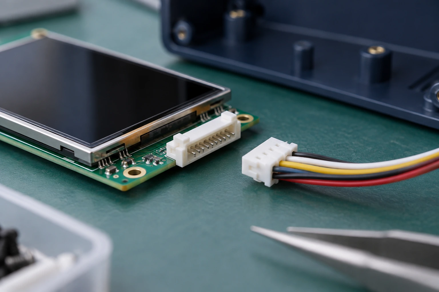
Explore three application scenes for compact electronics, appliance control boards and industrial equipment. Match the wafer header, wire housing and terminals to the requirements of the finished assembly.

Compact Electronic Devices — illustrative scene

Compact Electronic Devices

Plan wire-to-board connections for displays, sensors and small electronic modules. Review connector height, PCB space and cable routing, together with the circuit count and assembly access needed for the device.
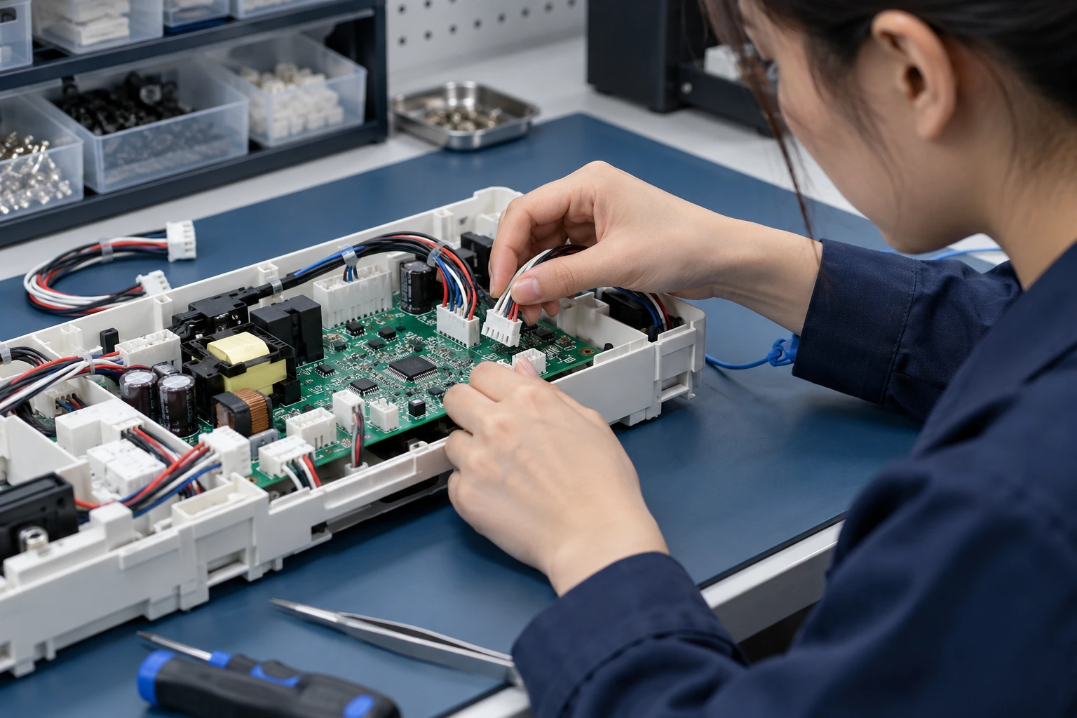
Appliance Control Boards — illustrative scene

Appliance Control Boards

Organize internal harness interfaces for appliance controls and electronic subassemblies. Define orientation, retention, wire requirements and the mating housing. Review ratings and soldering requirements for the exact selected configuration.

Industrial Equipment & Controls — illustrative scene

Industrial Equipment & Controls

Review board-mounted harness connections for controllers, instruments and equipment modules. Share current, temperature and vibration requirements and the access needed for service. Evaluate the complete connector pair in your assembly.

Wafer Connector Specifications: What to Confirm

Use this checklist to define the connector interface, board footprint and mating requirements. Review performance against the selected model datasheet.

SpecificationInformation to Confirm
Pitch & circuit countContact center spacing, positions, row arrangement and pin numbering
Mounting styleSMT or through-hole; vertical or right-angle orientation as specified by the model
PCB footprintPad or hole dimensions, board thickness, locating features and housing clearance
Mating componentsExact wire housing, crimp terminal, keying and retention arrangement
Wire & cable detailsConductor size, insulation diameter, cable routing and crimp requirements
Electrical & environmental needsCurrent, voltage, temperature and operating conditions for the exact configuration
Materials & assembly processContact plating, housing material, soldering profile and inspection criteria
Packing & supplyBag, tube, tray or tape-and-reel where available; packing quantity, labels and destination

Review the approved drawing, mating assembly and sample before ordering. Request the technical documents required for your selected connector.

Make Quality Part of the Purchase Specification

Pitch & Footprint Review

Check contact spacing, pin layout and mounting dimensions against the PCB design. Confirm the model drawing rather than identifying the header by appearance alone.

Complete Mating Assembly

Review the wafer header together with the wire housing and contacts. Keying, terminal retention and mating geometry must be checked alongside pitch and circuit count.

Wire & Crimp Requirements

Define conductor size, insulation diameter and the compatible crimp terminal. Review wire preparation and tooling requirements for the selected contact.

Material & Soldering Fit

Specify housing and plating requirements and the planned board assembly process. Confirm model-specific soldering and handling information before production approval.

Sample & Retention Checks

Evaluate a sample in the actual board and harness. Check mating, retention, cable routing and the electrical or environmental tests required for your assembly.

Pin Protection & Traceability

Choose packing that protects contacts, solder tails and housing features. Define part references, lot information, quantity and receiving inspection requirements.

Select Wafer Connectors in Six Practical Steps

1. Confirm Pitch & Circuits

Share contact spacing, pin count and row arrangement. Provide a drawing, sample or original reference to distinguish similar configurations.

2. Choose the Board Mount

Select SMT or through-hole mounting around the PCB and assembly process. Confirm pad or hole layout and any board locating features.

3. Plan Orientation & Clearance

Define vertical or right-angle entry, connector height and cable routing. Allow space for mating, retention access and service handling.

4. Specify Circuit Conditions

Describe operating current, voltage, temperature and environment. Review required material and performance information for the exact connector pair.

5. Match Housing & Terminals

Confirm the wire housing, contacts, wire dimensions and tooling. Review a complete mated sample on the intended board and harness.

6. Confirm Packing & Supply

Agree quantity, packing format, labels and destination. Confirm MOQ, samples, price, lead time and shipment terms in the quotation.

Get Your Free Sample!

We provide samples for free, you just need to tell us what you need

Wafer Connector Workshop & Packaging

Wafer Connector Assembly & Inspection — illustrative scene

Wafer Connector Assembly & Inspection

Discuss the approved header drawing, contact alignment and housing requirements with TONFUL. Define dimensional checks, pin positioning, mating review and sample inspection around the selected configuration. Agree the inspection records required for your purchase specification.

Pin Protection & Shipment Packing — illustrative scene

Pin Protection & Shipment Packing

Protect fine contacts, solder tails and housing edges during handling and delivery. Discuss bag, tube, tray or tape-and-reel packing where available for the selected model. Confirm packing quantities, part labels and outer-carton protection before shipment.

Illustrative workshop and packaging scenes.

More Than Just a Wafer Connector Manufacturer

Service Consultation — illustrative scene

Service Consultation

Send pitch, circuit count, board layout and mating requirements. TONFUL can review the wafer connector configuration and the drawings and samples needed to prepare a quotation.
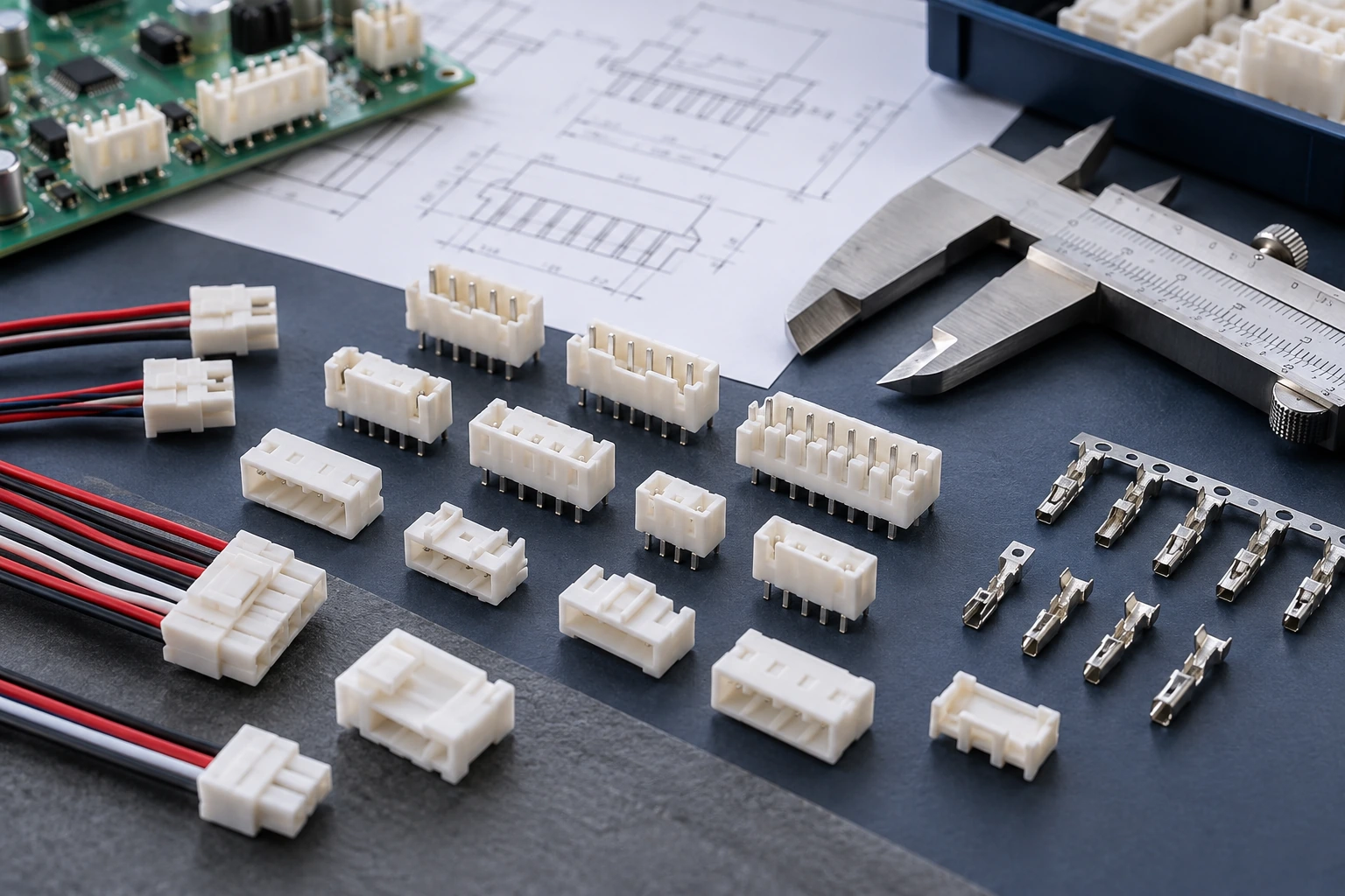
Product Recommendations — illustrative scene

Product Recommendations

Compare mounting style, orientation and housing geometry around your assembly. Original references and sample dimensions help identify relevant connector and mating-component options.
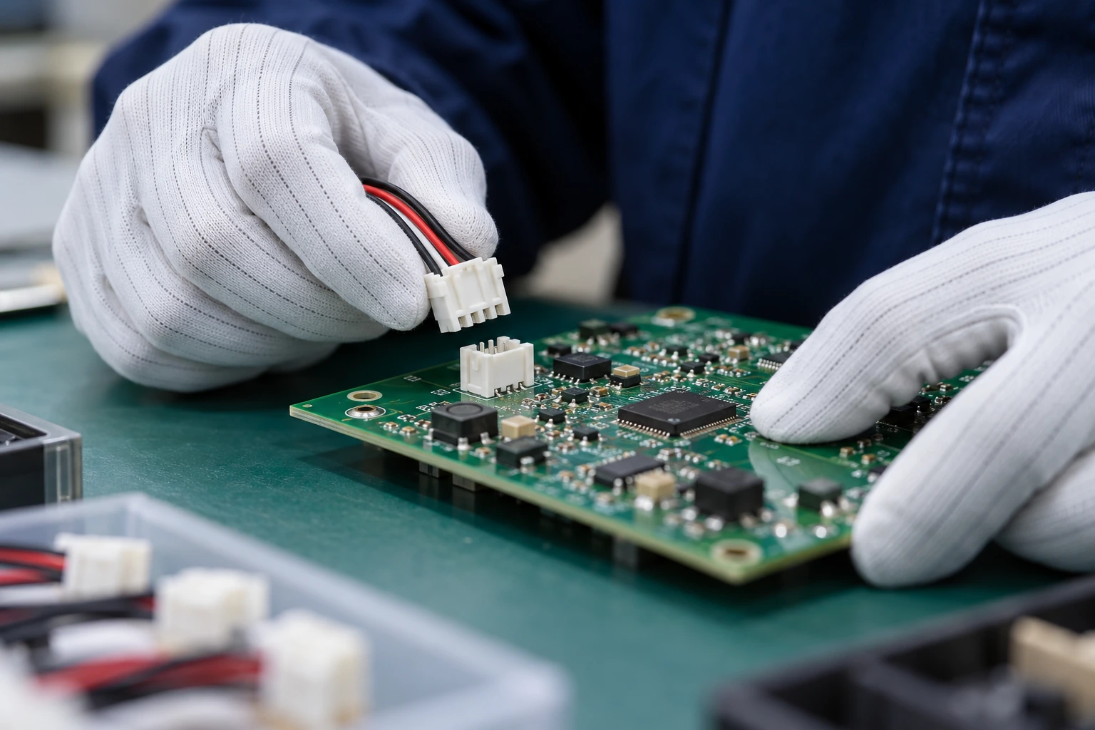
Assembly Support — illustrative scene

Assembly Support

Discuss header mounting, wire housing and crimp-contact information for the selected configuration. Share your assembly process and inspection criteria so applicable handling and technical documents can be reviewed.

Logistics Support — illustrative scene

Logistics Support

Share packing preferences, quantities and destination. TONFUL can review protective packing and shipping options; freight charges, shipment schedule and delivery terms are confirmed in the quotation.

Wafer Connectors: Frequently Asked Questions

What is a wafer connector?

In this catalog, it is a board-mounted header used with a compatible wire housing and contacts to form a wire-to-board connection. The model drawing defines the pitch, orientation and mating geometry.

How do I choose the correct pitch?

Measure contact center spacing and confirm the PCB and mating housing drawings. Pitch must be reviewed with circuit count, housing shape, keying and contact dimensions.

Can a similar-looking connector replace another brand?

Review the exact mating assembly and PCB footprint before approving an alternative. Matching pitch or appearance does not establish interchangeability or original-brand status.

What is the difference between SMT and through-hole versions?

SMT versions use board surface pads, while through-hole versions use plated board holes for their solder tails. Select the exact footprint and assembly requirements from the model drawing.

Can TONFUL supply matching housings and contacts?

Send the header reference and the required wire housing, terminal and wire details. Confirm which components and any harness assembly services are included in the quotation and approved packing list.

Is tape-and-reel packaging available?

Packing depends on the selected model. Share the assembly format, reel requirements and order quantity so available bag, tube, tray or tape-and-reel options can be confirmed.

How are current ratings and soldering temperatures confirmed?

Request the datasheet and assembly information for the exact configuration. Review the connector, terminals and wire together rather than applying a family-level rating to every variant.

What should I send for an OEM or wholesale quote?

Provide pitch, circuit count, orientation, mounting style, PCB footprint, mating parts, operating requirements, quantity and destination. Drawings or samples help clarify the configuration.

Request Wafer Connector Information

Plan your next wafer connector order with TONFUL Electric. Share pitch, circuit count, PCB footprint, mating housing, wire details, packing preferences and purchase quantity.

Explore related PCB connectors for additional board connection requirements.

Email ivan@tonful.com or open the enquiry window below.

滚动至顶部

Ask For Quote Now