
Box Header Connector Manufacturer for OEM & Wholesale
Source shrouded box headers and ejector headers from TONFUL Electric for PCB connections, ribbon cable interfaces and equipment assemblies. Compare six catalog configurations, then share your pitch, circuit count, mounting orientation, mating socket and order quantity.
Box Header Connector Product Range
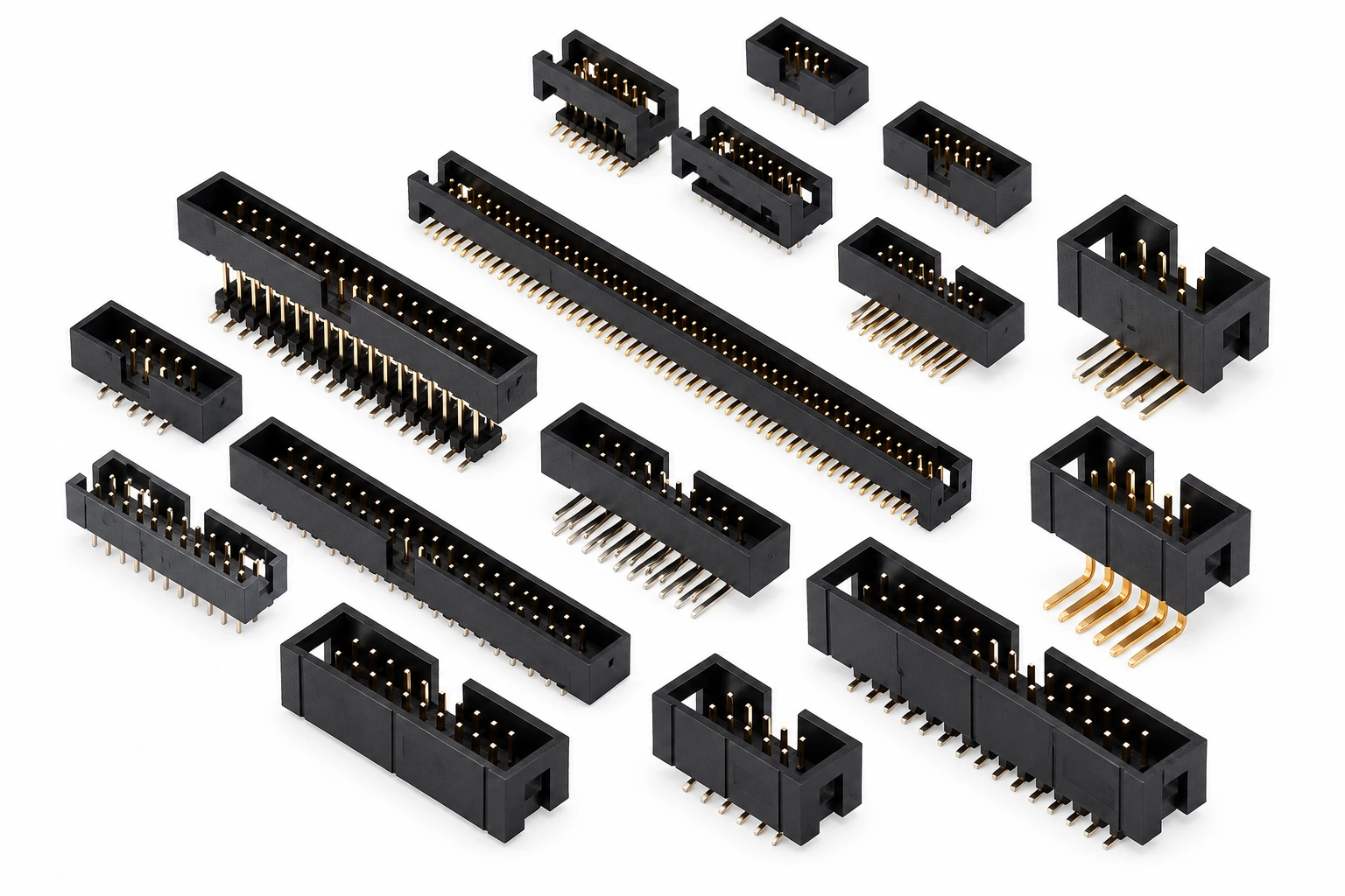
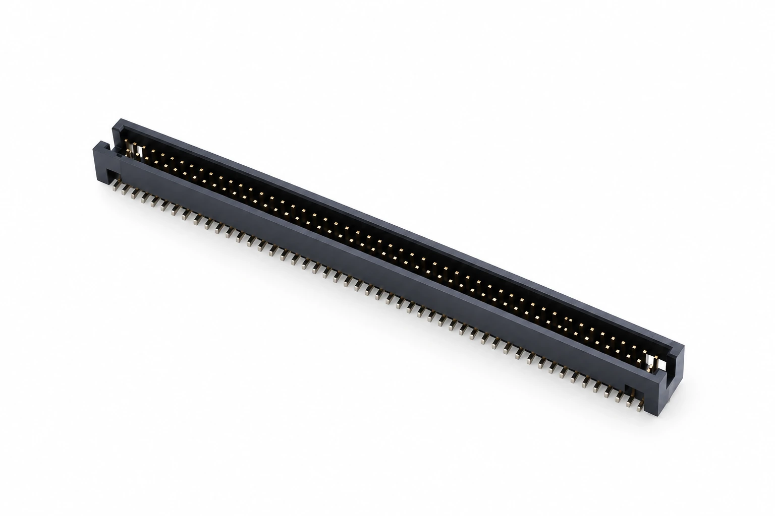
Compare six configurations covering 1.27 mm, 2.0 mm and 2.54 mm pitch, ejector latches, right-angle mounting and vertical mounting. Use the approved drawing to confirm the complete interface.

1.27 mm Box Header
Fine-pitch shrouded header configuration from the existing catalog. Confirm contact count, footprint, mating socket and mounting drawing.
2.0 mm Box Header
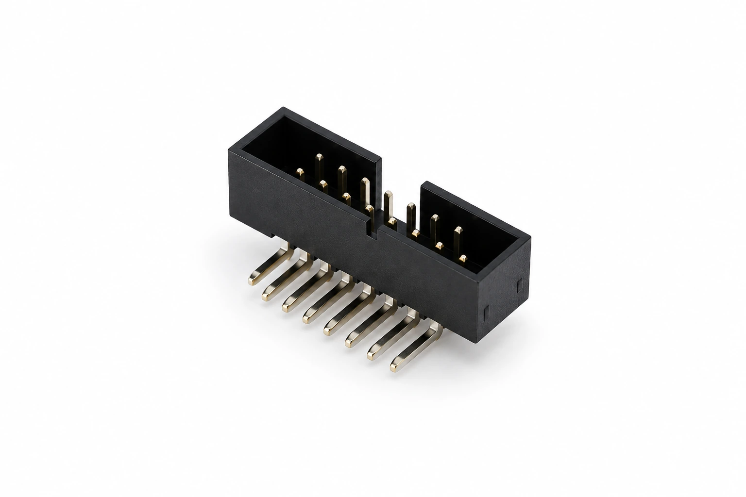
2.0 mm pitch shrouded header configuration. Confirm contact count, mounting orientation, mating socket dimensions and polarization.
2.54 mm Ejector Header
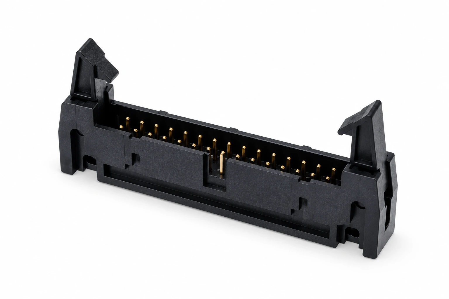
2.54 mm pitch header with ejector levers. Check contact count, mating socket retention and the clearance required to operate both latches.
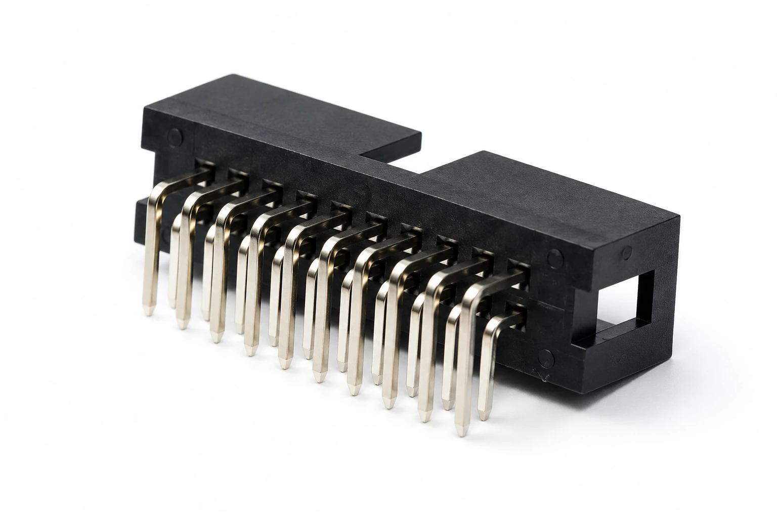
2.54 mm 2 × 10 Right-Angle DIP Box Header
2.54 mm pitch, dual-row 2 × 10, right-angle through-hole configuration. Review the hole layout, cable exit direction and solder-tail dimensions.
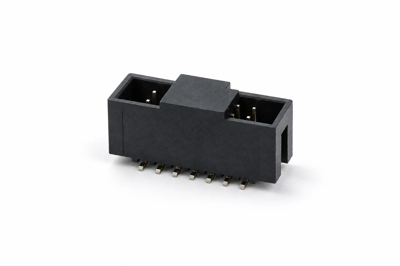
2.54 mm 2 × 7 Vertical SMT Box Header
2.54 mm pitch, dual-row 2 × 7, vertical SMT configuration. Confirm pad geometry, housing height and pickup features for the assembly process.
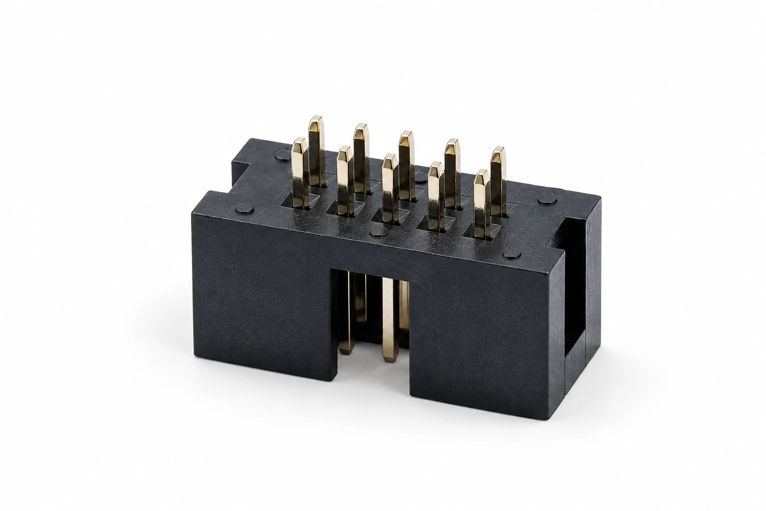
2.54 mm 2 × 5 Vertical DIP Box Header
2.54 mm pitch, dual-row 2 × 5, vertical through-hole configuration. Verify the PCB hole layout, mating depth and pin numbering.
Product names identify the catalog configurations shown. Confirm pin numbering, footprint, shroud dimensions, polarization and mating socket before sample approval.
Box Header Connector Applications
Explore three application scenes for shrouded PCB headers and ribbon cable connections. Select the connector against the electrical, mechanical and assembly requirements of the finished equipment.

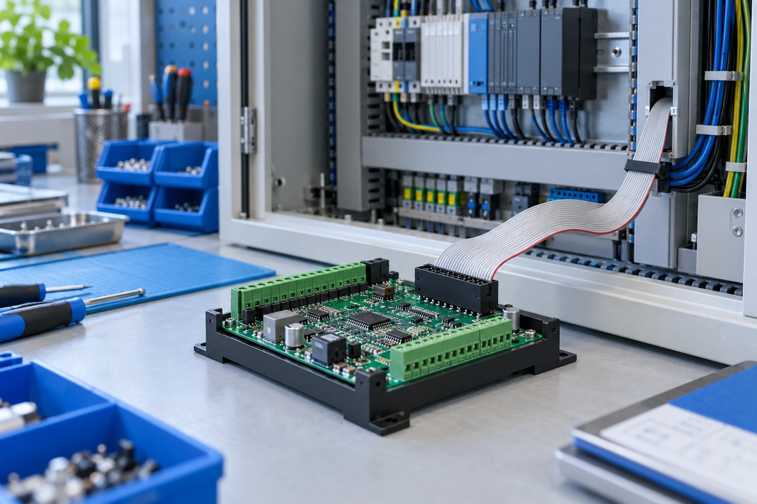
Industrial Control & Automation
Connect internal control boards and ribbon cable assemblies in automation equipment. Confirm circuit assignment, connector retention, vibration requirements and access for assembly and servicing.
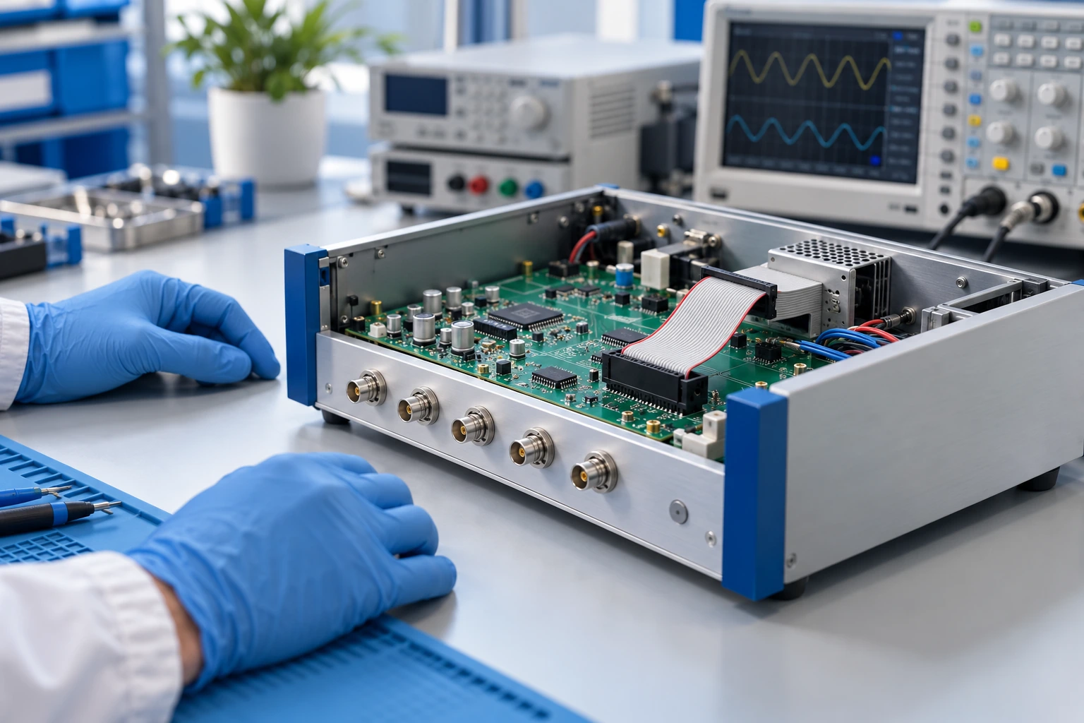
Test Instruments & Measurement Equipment
Review box header interfaces for measurement boards, signal modules and front-panel assemblies. Match pin numbering, cable routing, grounding and signal requirements to the complete equipment design.
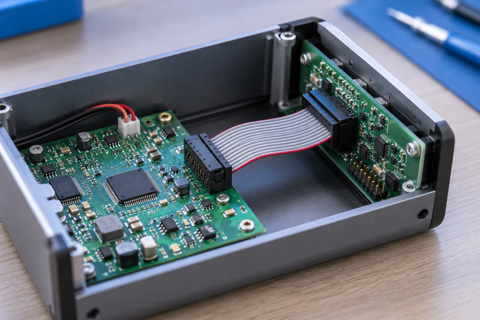
Embedded Electronics & Internal Connections
Use shrouded headers for compact board interfaces and internal cable connections. Check mating height, enclosure clearance, polarization and soldering requirements before approving the selected configuration.

Box Header Connector Specifications: What to Confirm
Use this checklist to define the connector interface, board footprint and mating requirements. Review performance against the selected model datasheet.
| Specification | Information to Confirm |
|---|---|
| Pitch & circuit count | The displayed catalog includes 1.27 mm, 2.0 mm and 2.54 mm configurations. Specify the number of rows and contacts using the selected drawing. |
| Mating interface | Provide the IDC socket or other approved mating connector reference, its polarization features and pin numbering. |
| Mounting orientation | Specify vertical or right-angle orientation, PCB entry direction, mating height and cable exit clearance. |
| PCB footprint | Confirm through-hole or SMT mounting, pad or hole locations, solder-tail dimensions and board thickness. |
| Shroud & latch geometry | Review keyway location, housing dimensions, ejector latch operation and the clearance needed to mate and unmate. |
| Materials & contact finish | Request housing material, contact material and plating details for the exact model and assembly process. |
| Electrical & environmental limits | Confirm current, voltage, temperature and other required performance limits from the selected model documentation. |
| Assembly & packaging | Agree on soldering instructions, pickup caps where applicable, packing format, carrier orientation and quantity per pack. |
Review the approved drawing, mating assembly and sample before ordering. Request the technical documents required for your selected connector.
Make Quality Part of the Purchase Specification
Drawing & Footprint Review
Match the approved connector drawing to the PCB holes or pads, mating height and assembly clearances.
Mating Socket Compatibility
Check pitch, contact count, polarization and pin numbering with the actual mating socket and cable.
Contact & Plating Details
Specify contact material, finish and inspection requirements for the selected model and application.
Shroud & Latch Inspection
Review housing condition, pin alignment, keyway geometry and ejector latch operation where fitted.
Assembly Process Check
Confirm soldering limits, mounting method and handling instructions before approving production samples.
Traceability & Packaging
Agree on part references, lot labels, contact protection and packing quantities before bulk supply.
Select Box Header Connectors in Six Practical Steps
1. Define Pitch & Circuits
Share the pitch, number of contacts, row arrangement and original reference or drawing.
2. Match the Mating Socket
Confirm the mating connector, keyway location and pin numbering together with the cable assembly.
3. Choose the Orientation
Specify vertical or right-angle mounting and the space needed for the connector and cable.
4. Review the PCB Footprint
Check through-hole or SMT mounting, tail dimensions, pad geometry and assembly requirements.
5. Confirm Materials & Finish
Provide contact plating, housing material and environmental requirements for model review.
6. Validate Samples & Supply
Evaluate mating samples, then confirm documentation, order quantity, packaging and lead time.
Get Your Free Sample!
We provide samples for free, you just need to tell us what you need
Box Header Connector Workshop & Packaging

Box Header Assembly & Inspection
Review the assembly and inspection plan for your selected box header configuration. Agree on housing dimensions, contact alignment, solder-tail condition and mating checks before bulk supply.
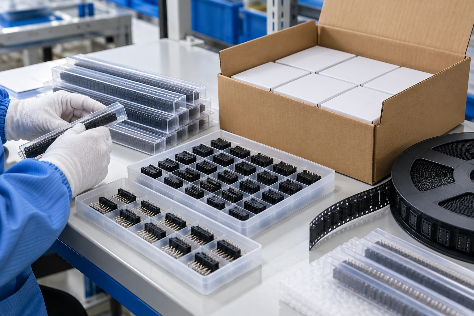
Protective Packaging & Order Identification
Discuss trays, tubes, tape-and-reel or other packing formats available for the selected model. Specify contact protection, carrier orientation, quantities per pack, part labels and shipment requirements.

Illustrative workshop and packaging scenes.
More Than Just a Box Header Connector Manufacturer

Service Consultation
Share your PCB layout, mating socket, cable routing and purchasing requirements so our team can review the box header enquiry.
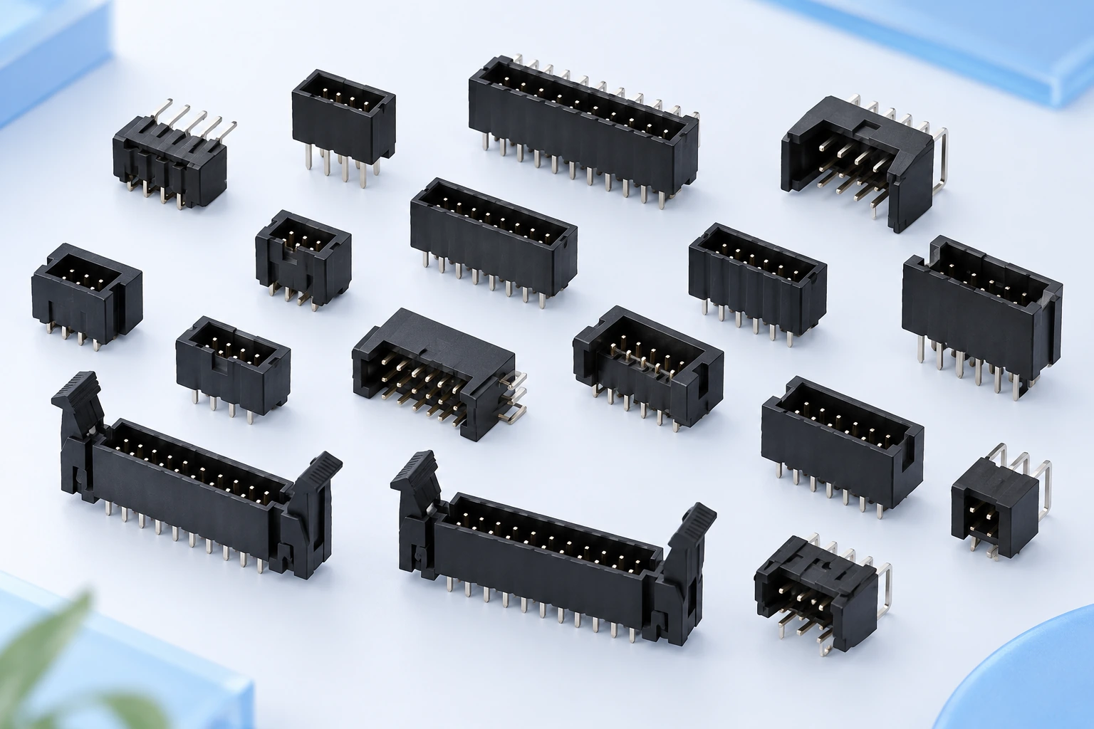
Product Recommendations
Compare pitch, contacts, mounting orientation and latch options. Request an approved drawing and sample to validate the connector selection.
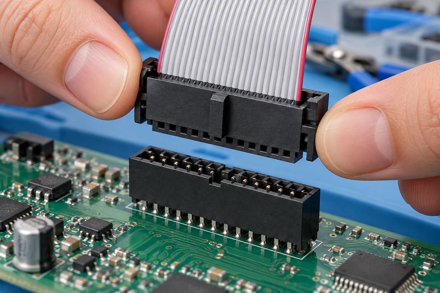
Assembly & Installation Support
Request the available soldering, mating and handling instructions for the exact configuration. Review assembly access and pin numbering before production.

Packaging & Logistics Support
Coordinate protective packing, part labels, carton requirements and shipment arrangements with the quotation and order specification.
Box Header Connectors: Frequently Asked Questions
What is the difference between a box header and an ejector header?
Both use a shroud around the contacts. An ejector header adds levers for retention and assisted removal of the compatible mating socket. Confirm latch geometry and the mating interface for the selected model.
Does matching pitch guarantee compatibility?
No. Confirm contact count, row spacing, shroud dimensions, polarization, pin numbering and mating depth as well as pitch. Validate the complete connector pair against drawings and samples.
How do I choose vertical or right-angle mounting?
Review the PCB position, enclosure space, cable exit direction and access for mating. The selected orientation must fit the PCB footprint and the assembled equipment.
Can all box headers be used in SMT reflow assembly?
Assembly suitability depends on the selected mounting type, housing material and product instructions. Request the soldering limits and approved footprint for the exact configuration.
What packaging options can I request?
Ask for the formats available for your selected model, such as tubes, trays or tape-and-reel. Confirm pickup features, carrier orientation, quantities and contact protection in the quotation.
What should I include in an OEM or wholesale enquiry?
Send the original reference or drawing, pitch, contact count, mounting orientation, PCB footprint, mating socket, intended application, quantity and packaging requirements. Confirm samples, MOQ, lead time and commercial terms with TONFUL.
Request Box Header Connector Information
Ready to review your box header connector requirements? Send the connector drawing, mating socket details, PCB footprint and order quantity to TONFUL Electric.
Explore PCB connectors, wafer connectors and custom cable assemblies for related connection requirements.
Email ivan@tonful.com or open the enquiry window below.
