
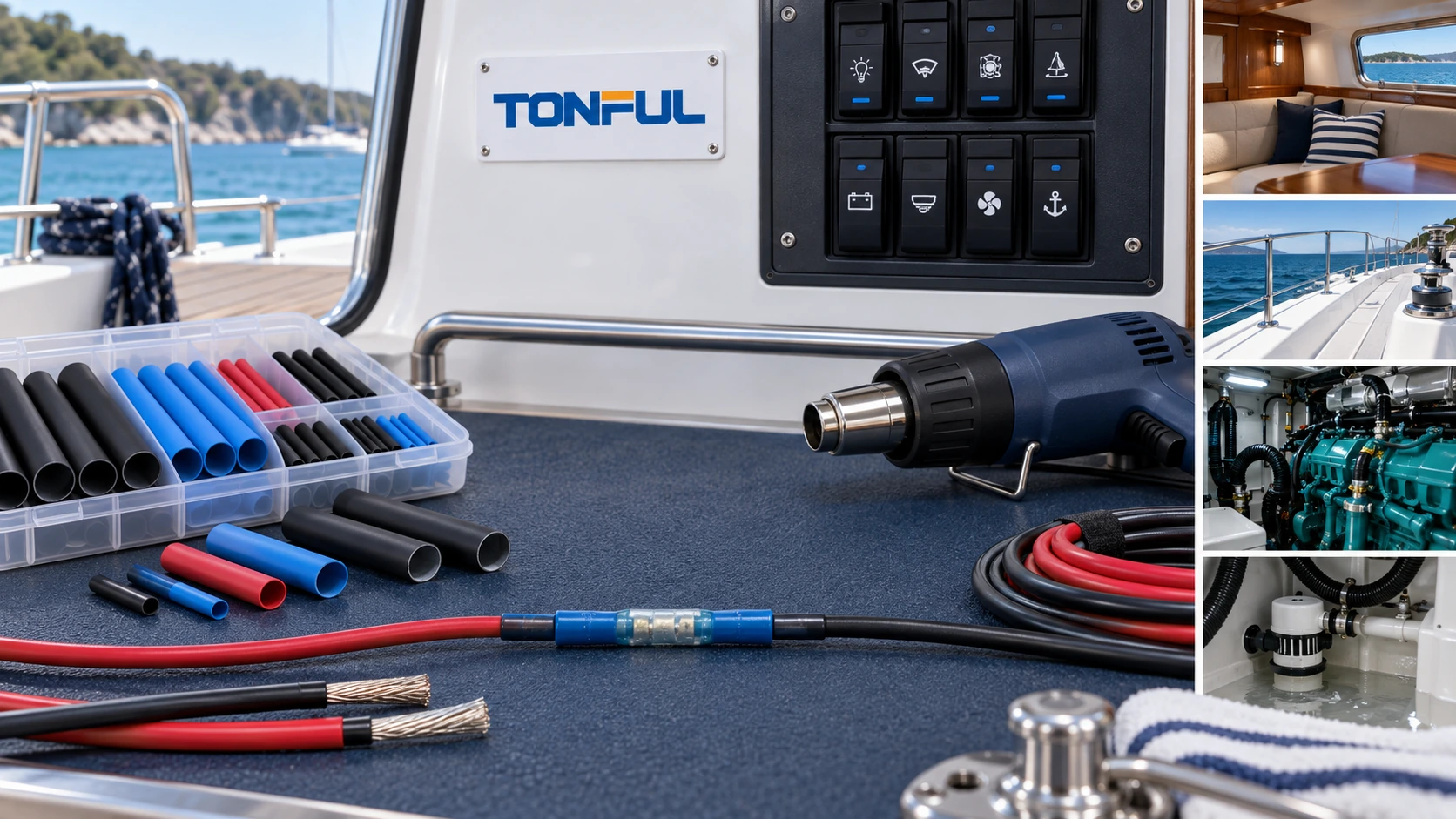
Marine heat shrink tubing should be selected for a defined circuit, location and exposure, not from a vague “marine grade” label. A protected cabin harness, a deck fitting, an engine-space splice and a connection exposed to bilge moisture can face very different combinations of salt, condensation, spray, vibration, heat and service access. The tube must also fit the actual conductor insulation, terminal geometry and production heating process.
This guide applies mainly to low-voltage DC boat wiring and harness assemblies. Shore-power, AC branch circuits, fuel spaces, ignition-protected equipment and regulated vessel systems require current equipment instructions, applicable codes and standards, and qualified personnel. Heat shrink tubing does not replace an approved conductor, terminal, overcurrent device, enclosure, cable support or required system inspection.
On this page: Exposure | Corrosion | Sealing | Sizing | Installation | Validation
Define the Real Marine Exposure
Record exactly where the tubing will operate. “Wet” can mean condensation inside a console, occasional splash on deck, pressure washing, bilge humidity, salt spray, temporary immersion or continuous submersion. Those conditions are not interchangeable. Also document temperature, UV exposure, fuel or oil contact, cleaning chemicals, vibration, flexing, conductor movement and access for inspection.
| Installation zone | Main concerns | Evidence needed |
|---|---|---|
| Dry cabin or protected console | Condensation, identification, serviceability and abrasion | Drawing, material identity and installation record |
| Deck or exposed compartment | Salt spray, UV, washdown and vibration | Assembly sealing and environmental evidence |
| Engine or machinery space | Heat, oil/fuel exposure, vibration and ignition-related restrictions | Location-specific material and safety requirements |
| Bilge or low point | Persistent moisture, contamination and water migration | Defined immersion/moisture test and routing review |
| Moving hatch or hinged harness | Flexing, chafe, strain and seal fatigue | Dynamic assembly test with production supports |
Do not turn an IP code, immersion demonstration or salt-spray result into a universal waterproof claim. The test specimen, exposure duration, pressure or depth, cable entry, conditioning and acceptance criteria must match the intended claim. The current applicable requirements should be identified from the vessel design documents and standards plan. The official ABYC standards list includes E-11 for AC and DC electrical systems on boats and other marine electrical topics, but the list itself is not a product approval or installation specification.

Marine wiring zones require different evidence because condensation, spray, immersion, heat, chemicals and movement do not create the same failure mechanism.
Understand How Corrosion Reaches a Splice
Corrosion begins when moisture and conductive contaminants reach exposed metal and an electrochemical path develops. Salt can increase conductivity and remain after visible water dries. Moisture may enter directly at a tube end, travel through a multi-wire valley, wick along conductor strands, migrate under insulation or arrive from an unsealed connector farther along the harness.
A liner cannot restore a conductor that is already blackened, green, pitted or mechanically weakened. It also cannot correct an undercrimp, cut strands, incompatible terminal, poor support or hidden water source. Before covering a repair, inspect enough conductor to find clean, mechanically sound material. Replace the affected section when corrosion has migrated beyond the proposed joint; do not hide uncertain damage under a longer sleeve.
Tinned copper can improve resistance to some marine corrosion mechanisms, but the words “tinned wire” do not prove the conductor, insulation or termination is suitable for every location. Verify conductor construction, stranding, temperature and voltage requirements, terminal compatibility, crimp tooling and project approval. Corrosion control is a system decision involving routing, drainage, sealing, support and inspection.
The tubing polymer and liner must also match the location. The heat shrink tubing material guide explains why a generic material family does not establish temperature, fluid, UV or flexibility performance for a specific product.

Conceptual illustration only—not an acceptance standard or laboratory micrograph. Moisture can enter through several paths, so the complete splice and surrounding harness must be evaluated.
What Adhesive-Lined Tubing Can and Cannot Do
Adhesive-lined tubing combines a heat-recoverable outer wall with an internal liner that softens during installation. With compatible, clean substrates and sufficient heat, the liner can wet the surfaces and fill limited gaps while the outer wall recovers. This can create a useful environmental barrier around a properly made splice.
The barrier is not automatic. Oils, release agents, oxidation, damp insulation or incompatible polymers can prevent adhesion. A cylindrical sleeve may bridge rather than fill deep valleys between wires. Too little overlap, insufficient liner volume or uneven heating can leave a capillary path. Excess liner can flow into connector features or conceal an incorrectly positioned crimp.
Use the adhesive-lined heat shrink guide to define liner and substrate controls. TE Connectivity’s official dual-wall tubing overview describes the general outer-wall and encapsulant concept and shows why products differ by application. Its product-family statements are not evidence of TONFUL ratings.
A visible adhesive bead is an installation indicator, not proof of waterproofing. Acceptance should combine controlled process evidence with the required leak, ingress, electrical and mechanical checks. If the application requires continuous immersion, an IP classification or a recognized marine-equipment approval, identify the exact claim and test basis before choosing the product.
Claim-to-Test Matrix
| Proposed claim | Evidence that should define it | What does not substitute for it |
|---|---|---|
| Moisture resistant | Defined humidity, condensation or splash conditioning | A dry visual inspection |
| Sealed splice | Production assembly and specified leakage/ingress test | Adhesive visible at one end |
| Salt exposure suitable | Defined salt concentration, cycle, temperature and post-test checks | Fresh-water immersion alone |
| Temporary immersion | Depth/pressure, duration, orientation and acceptance criteria | Spray or washdown test |
| IP rating | Applicable IP method for the exact assembly and boundaries | Supplier wording without report scope |
| Approved wire combinations | Tested conductor count, size, insulation and terminal geometry | Fit on one convenient sample |
Size the Tube for Pass-Over and Recovered Fit
The supplied inside diameter must pass over the largest feature, commonly the crimp barrel, terminal shoulder or connector feature. The recovered diameter must then grip and seal the smallest required substrate without relying on an uncontrolled amount of adhesive. Measure real maximum and minimum production parts rather than nominal wire size alone.
Check recovered wall and liner distribution, not only diameter. A high shrink ratio can help pass over a large barrel, but it does not guarantee uniform wall, centered recovery or valley filling. Excessive oversizing can increase recovery time, liner movement and wrinkles. Use the heat shrink size guide to document pass-over diameter, substrate diameter, overlap and recovery margin.
Account for longitudinal change when positioning the cut piece. Specify the required overlap onto intact insulation at both ends and keep sleeve edges away from peak flex zones. On multi-wire exits, use a validated branch-sealing design rather than assuming one round tube will close every channel.
Install a Sealed Marine Splice
De-energize and isolate the circuit according to the vessel and equipment procedure. Confirm the correct circuit, protect against unintended reconnection and verify the work area is free from fuel vapors or other flammable hazards. Never use an open flame. A controlled hot-air tool can still ignite materials or damage insulation, so use appropriate ventilation, guarding and personal protection.
- Inspect the wiring route, water source, conductor condition and available support. Correct the root cause before installing a new joint.
- Cut back to clean conductor where the approved repair permits it. Select the specified terminal, tube, conductor combination and calibrated crimp tooling.
- Place the tubing on the wire before crimping. Strip without nicking strands, complete the crimp and perform required visual, dimensional or pull verification.
- Center the tube with the specified overlap. Keep adjacent seals, plastic housings and sensitive components outside damaging heat.
- Heat progressively around the circumference and along the tube using the validated tool, nozzle, distance and motion. Avoid scorching, trapped air and pushing the liner away from the seal zone.
- Allow the joint to cool without bending or loading it. Inspect position, recovery, liner condition, wrinkles, splits, exposed conductor and heat damage.
- Complete the required electrical and sealing checks, restore harness support and record the repair identity.

A repeatable marine splice process controls conductor condition, crimping, overlap, heating, cooling, inspection and final electrical verification.
The U.S. Coast Guard’s Boatbuilder’s Handbook wiring diagrams provide official general context for boat electrical systems. They do not approve a particular heat shrink product or replace the vessel’s controlled diagram and service procedure.
Route and Support the Finished Joint
Position the splice above predictable water collection points where the design allows, and route the harness so water does not naturally drain toward the joint. Do not create a sealed pocket that traps moisture beside the sleeve. Maintain the approved drip path, bend radius, separation and mechanical protection.
Support the harness so the splice is not a hinge, handle or strain-relief substitute. Repeated movement at a stiff sleeve edge can fatigue conductors. Keep it away from sharp edges, moving linkages, hot surfaces and crushing loads. Use approved clips and leave service slack without creating a loose loop that chafes.
After installation, inspect the surrounding connector seals, grommets, deck penetrations and enclosures. A perfect local sleeve cannot prevent water entering elsewhere and wicking along the cable. Maintenance records should identify recurring wet locations instead of treating every corroded splice as an isolated component failure.
Validate the Completed Assembly
Test production-representative conductors, insulation, terminals, crimps, tube, liner and heating process. Include tolerance extremes and every approved wire combination. State sample quantity, sequence, unaged controls, destructive-analysis allocation, invalid-test rules and who approves replacements. Do not replace a valid failure with a convenient retest.
| Validation area | Controlled record | Required result source |
|---|---|---|
| Sample identity | Tube lot, wire, terminal, crimp tool/cavity and sample ID | Approved drawing or plan |
| Installation | Cut length, overlap, heat tool, nozzle, setting and operator | Work instruction |
| Baseline electrical | Continuity, resistance or loaded voltage-drop setup | Circuit/product requirement |
| Moisture or salt | Medium, concentration, temperature, duration, orientation and cycling | Qualification plan |
| Thermal conditioning | High/low conditions, dwell, transitions and sequence | Project specification |
| Flex or vibration | Supports, bend, input and monitoring | Installation-specific plan |
| Retention | Fixture, pull direction, rate and failure mode | Terminal/assembly requirement |
| Sectioning | Location, preparation, voids, wetting and damage observations | Engineering criteria |
| Final disposition | Raw results, deviations, reviewer and approval date | Controlled acceptance record |
Measure initial and conditioned results using the same defined setup. If resistance or voltage drop is important, specify probe positions, current/load, temperature, lead compensation and whether conductor reference resistance is removed. A visual seal cannot establish electrical stability. The heat shrink testing guide explains how to preserve repeatable records.

The validation record keeps construction, conditioning, raw results and acceptance sources traceable for each production-representative sample.
Release, Inspection and Maintenance
Release the exact product, size, color, liner, conductor insulation, terminal, overlap and installation process. Define incoming identity checks, lot traceability, storage limits, first-piece approval and reaction rules for incomplete recovery, scorching, splits, incorrect position or abnormal liner flow. The bulk heat shrink sourcing guide covers lot and packaging controls.
During vessel inspection, look for cracked tubing, lifted ends, swelling, discoloration, green or white deposits, overheated insulation, stiffness, water tracks and unsupported movement. Investigate the circuit before resealing. Repairs should not be stacked indefinitely over unknown joints; replace the affected section or harness when damage, access or configuration prevents a controlled repair.
Supplier changes to resin, adhesive, pigment, dimensions, cross-linking, expansion, manufacturing site or test method can affect a validated seal. Require change notification and define requalification based on risk. Field performance should be tracked by location, lot, installation process and failure mechanism rather than by a generic “waterproof connector” category.
Work With TONFUL
Send TONFUL the boat application, circuit type, conductor and terminal details, pass-over and substrate dimensions, exposure profile, sealing claim, installation process, validation requirements and annual volume. TONFUL can discuss available heat shrink tubing options and production-intent samples. Final ratings, certifications and approval scope must be confirmed for the exact quoted product and completed assembly.
—
