
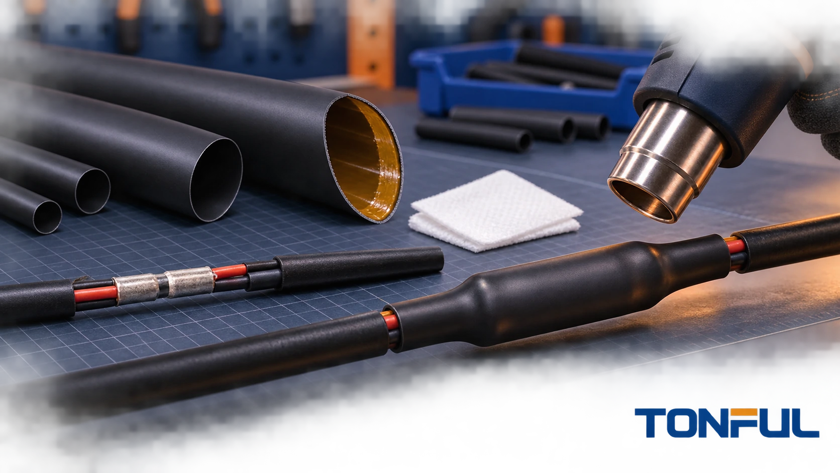
Adhesive-lined heat shrink tubing can protect a splice or cable transition by combining a recoverable outer wall with an inner thermoplastic adhesive or sealant. During controlled heating, the outer wall shrinks while the liner softens, wets compatible surfaces and fills some available gaps. A successful result depends on the complete joint: tubing, liner, substrate, geometry, cleanliness, overlap, heating process and validation method.
The presence of adhesive does not automatically make an assembly waterproof, IP-rated, suitable for immersion or approved for every cable jacket. This guide explains how to select and validate adhesive-lined tubing without turning a material feature into an unsupported system claim.
On this page: Construction | Substrates | Geometry | Installation | Validation | RFQ record
Understand the Two-Layer System
Recoverable Outer Wall
The outer wall provides radial recovery and much of the mechanical, thermal and environmental behavior. Cross-linked polyolefin is common, but material, thickness, flexibility, color, flame evidence and operating conditions vary by product. Select it from the exact drawing and data sheet rather than from the general term “dual wall.”
Adhesive or Sealant Liner
The liner softens during heating and is displaced by the recovering outer wall. Its role may include bonding, gap filling, moisture-path reduction and strain transition. Liner chemistry, viscosity, amount and activation conditions affect performance. A product with a thin liner intended for light sealing is not equivalent to a heavy-wall cable sleeve with a large sealant volume.
TE Connectivity’s official HTAT adhesive-lined tubing family illustrates why selection must remain part-number specific: expanded and recovered dimensions, packaging and product documents vary within one family. That page is an external example, not proof of a TONFUL product rating.
The single-wall versus dual-wall heat shrink guide helps determine whether an internal liner adds project value.
Verify Substrate Compatibility
Identify Every Contact Surface
List wire insulation, cable jacket, molded connector, terminal metal, braid, paint, potting compound, existing adhesive and any label beneath the tube. A transition can contain several materials, and the liner may wet each differently. PVC, cross-linked polyolefin, nylon, rubber, silicone and fluoropolymers should not be assumed to have equal adhesion.
If the project requires a bonded seal, obtain compatibility evidence or test production materials. A result on one black cable jacket does not automatically cover another supplier, compound, texture or aged surface.
Control Surface Condition
Oil, mold release, fingerprints, oxidation, water, dust and process residue can interrupt wetting. Define handling and cleaning in the work instruction. Use only cleaners approved for the tubing liner and substrates. An aggressive solvent can crack insulation, remove printed identification, swell a seal or leave residue.
Surface abrasion or primer should be used only when the product and assembly procedure permit it. Record material, method, drying time and environmental controls. Do not improvise preparation on production parts after a sealing failure.
Consider Aged and Contaminated Repairs
Field repairs often involve weathered cable jackets, corrosion or absorbed fluids. Cleaning can improve the surface but may not restore it to new-material condition. Inspect the conductor and insulation damage before covering the area. Heat shrink must not hide an unresolved electrical, crimp or corrosion defect.
The marine heat shrink tubing guide provides additional context for salt, corrosion and service environments.
Design the Sealing Geometry
Create Continuous Sealing Lands
The liner needs sufficient clean, compatible surface beyond the joint on each side. There is no universal overlap length. Define it from the splice or connector design, tube size, liner volume, cable tolerance, bending and qualification plan. Keep sharp edges and abrupt steps away from the end seal when possible.
For a connector backshell, confirm that the tube does not cover a release feature, vent, latch or service interface. For a splice, ensure the tube covers the conductive barrel and any insulation transition required by the drawing without creating an excessively stiff bend point.
Account for Multi-Wire Valleys
Several round wires create valleys that may remain open even when the outside of the tube looks fully recovered. Adhesive can flow into some spaces, but capillary paths may remain between conductors. Bundle arrangement, conductor count, insulation diameter and liner volume must be controlled.
Where sealing is critical, use a designed breakout, potting, molded part or product specifically qualified for the geometry. Do not assume a cylindrical tube can seal any branch. Section development samples or use the specified leakage/ingress test to assess internal coverage.

Conceptual illustration only—not a laboratory cross-section or acceptance standard.
Size for Pass-Over and Recovery
Select minimum expanded ID to clear the largest feature and maximum recovered ID below the smallest sealing surface. For irregular transitions, a 3:1 or 4:1 product may be appropriate, but ratio does not prove liner performance. Use the heat shrink tubing size guide and the selected product drawing.
Excessively large tubing can consume recovery before developing the intended pressure on the substrate. Undersized tubing may stretch during installation or split during heating. Recovered wall and adhesive displacement must remain acceptable at both tolerance extremes.
Control the Installation Process
Define Equipment and Thermal Boundaries
Use a qualified heat gun, oven, infrared system or other controlled equipment. Open flame is not an appropriate default process because it creates concentrated heat, soot and ignition risk. Identify heat-sensitive wire insulation, connector seals, solder, labels and electronics before setting the process.
The heat-source setting is not the same as tubing or substrate temperature. Define equipment, nozzle or zone, distance or conveyor speed, fixture, orientation, heating sequence and endpoint. Confirm that metal terminals do not leave the liner cold while nearby polymers overheat.
Use a Controlled Heating Sequence
The sequence should encourage air and excess adhesive to move toward an exit rather than trapping a pocket. The correct starting point depends on joint geometry and product instructions. For a straight splice, development may show that controlled movement from the center toward the ends is effective; a connector transition may require another sequence. Document the validated method rather than publishing one universal rule.
Rotate or fixture the assembly to achieve circumferential heating where required. Do not hold the heat source in one location until the outer wall glosses, scorches or blisters. Continue only until the defined recovery and liner endpoint is reached.
Define Visual Acceptance
Inspection can include final position, complete outer-wall recovery, absence of splits, holes, scorching and unacceptable wrinkles, and specified adhesive appearance. A continuous small bead may indicate flow at the ends. Excessive extrusion can indicate too much heat, incorrect size or liner displacement. No visible bead may be acceptable for some products and a warning sign for others.
Visual criteria must come from validated samples or the product/application specification. They cannot prove internal wetting by themselves. The heat shrink ratio guide explains why ratio and geometry affect the process.

The workflow requires inspection against defined criteria and does not impose a universal adhesive-bead rule.
Validate the Completed Assembly
Separate Demonstration From Qualification
A water-bead demonstration, brief immersion or attractive cutaway can teach the concept but does not establish long-term sealing. Qualification should represent the exact substrates, tubing size, process and failure risks. Define conditioning, sample allocation, test method, equipment, acceptance criteria and post-test inspection.
Depending on the project, validation may include:
- Visual and dimensional inspection before conditioning.
- Electrical insulation or resistance measurements where applicable.
- Water, humidity, salt, fluid or pressure exposure defined by the customer plan.
- Thermal cycling or aging followed by retest.
- Flex, pull, strain or vibration appropriate to the assembly.
- Sectioning to review adhesive distribution, voids and substrate contact.
Do not label an AI-generated cutaway as a laboratory cross-section. Real evidence needs sample identity, tube and substrate details, section location, scale, raw-image reference and acceptance source.
Understand IP Boundaries
An IP code is assigned using a defined enclosure/interface configuration and test method. Tubing material by itself does not receive every assembly rating claimed in marketing. If an IP requirement applies, record the tested complete assembly, dimensions, preparation, installation, report and permitted variations.
UL Solutions’ insulating tubing testing and certification overview describes evaluation of submitted tubing products, including constructions with meltable liners. It does not turn every adhesive-lined assembly into a certified seal.

Visible flow, moisture resistance, an IP rating and approved substrates require different evidence and are not interchangeable claims.
Control Production and Rework
Monitor tubing and liner identity, lot, storage, cut length and work-in-process exposure. Where shelf life applies, use the manufacturer’s documented basis and control first-expiring material. Protect liners from dirt and deformation during cutting and handling.
For production, verify first piece, tool or equipment changes, material changes and restart conditions according to the control plan. Record nonconforming adhesive flow and reaction rules. If a supplier changes outer polymer, liner, wall or process, require notification and determine whether requalification is necessary.
Rework must be authorized. Cutting away bonded tubing can damage insulation, seals or plating. Inspect and clean the substrate using an approved method, then repeat required tests. Do not install a second tube over an unknown failed seal merely to hide it.
The bulk heat shrink tubing sourcing guide covers lot traceability, packaging and change control.
Adhesive-Lined Tubing RFQ and Release Record
| Record field | Required entry |
|---|---|
| Application | Splice, connector, cable end, branch or repair and failure consequence |
| Substrates | Exact materials, suppliers, surface condition and tolerance |
| Tubing | Manufacturer, series, part number, outer polymer, liner and color |
| Dimensions | Expanded/recovered ID, total/outer wall, ratio and length change |
| Seal geometry | Minimum lands, overlap, valleys, branches and sharp edges |
| Preparation | Handling, cleaner, abrasion/primer permission and drying |
| Installation | Equipment, fixture, sequence, process limits and endpoint |
| Inspection | Position, damage, wrinkles, adhesive appearance and internal evidence |
| Qualification | Samples, conditioning, tests, acceptance source and results |
| Supply control | Lot, packaging, storage, shelf life and change notification |
| Release | Approved scope, deviations, reviewer and date |
Discuss Adhesive-Lined Tubing With TONFUL
Send TONFUL the substrate materials, largest and smallest diameters, joint geometry, moisture and fluid exposure, wall and ratio preference, required tests, cut length, packaging and volume. TONFUL can discuss candidate adhesive-lined products and samples within its documented supply range. Final release should remain limited to the validated product, assembly and heating process.
