
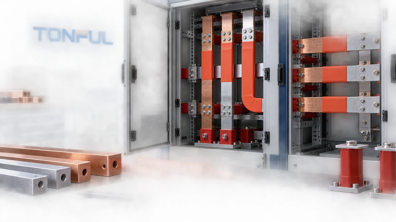
Busbar heat shrink tubing is a component in an insulation system, not a universal method for assigning a voltage rating or reducing clearance. The correct sleeve depends on system voltage, transient stress, bar geometry, insulation coordination, pollution, temperature, joints, supports, installation process and the approved equipment design. A red or orange tube that fits the bar is not automatically suitable for switchgear service.
This guide explains how engineers and buyers should define busbar insulation tubing for low- and medium-voltage equipment. It does not provide live-work instructions or universal clearance reductions. Busbar preparation and heating must be performed on isolated, locked-out, verified-de-energized equipment by qualified personnel under the equipment manufacturer’s procedure and applicable electrical-safety rules.
On this page: System | Geometry | Sizing | Design | Installation | Validation
Define the Electrical System and Insulation Purpose
Begin with the equipment, not the tube catalog. Record nominal and highest system voltage, AC or DC, frequency or waveform, phase configuration, grounding, overvoltage category or system transient basis, required withstand levels, altitude, enclosure, pollution environment and applicable equipment standard. For power-electronic systems, repetitive high-frequency or non-sinusoidal stress may require additional analysis.
Then state the purpose of the sleeve. It may provide supplemental insulation, protect against accidental bridging, improve resistance to tracking or contamination, support phase identification, or form part of a validated clearance-reduction design. Those functions have different evidence requirements. Heat shrink must not be described as basic, supplementary or reinforced insulation unless the equipment design and applicable standard support that classification.
| Design question | Required project input | Why it matters |
|---|---|---|
| What voltage stress applies? | System, transient and withstand requirements | Nominal voltage alone is incomplete |
| What insulation function is intended? | Functional, supplemental or equipment-defined role | Determines evidence and acceptance scope |
| Where is the bar installed? | Indoor/outdoor, enclosure and pollution conditions | Surface contamination affects tracking risk |
| What is the altitude? | Installation altitude and correction method | Air clearances can require correction |
| What equipment governs approval? | Switchgear/panel standard, drawing and test plan | Component data cannot approve the assembly |
For low-voltage equipment, IEC 60664-1:2020 addresses insulation coordination up to AC 1,000 V or DC 1,500 V, including principles for clearances, creepage and solid insulation. For three-phase AC systems above 1 kV, IEC 60071-1:2019 addresses selection of rated withstand voltages for insulation coordination. These horizontal standards do not provide a universal tubing selection or establish human-safety requirements for a finished switchgear assembly.

Busbar tubing selection begins with the electrical system and insulation purpose, not with color, nominal bar width or a generic voltage label.
Record the Complete Busbar Geometry
Create a controlled drawing of every insulated segment. Record copper or aluminum, bar width and thickness, diameter for round bars, tolerances, bends, edge radius, holes, bolts, splice plates, flexible links, supports, stand-offs and nearby grounded or phase conductors. Note the maximum envelope that the supplied tube must pass over and the minimum cross-section it must recover onto.
Rectangular bars deserve special attention. A tube selected from bar width alone may fit poorly because its circular supplied diameter must pass over the diagonal of the rectangle and any bend or joint. During recovery, the material stretches across corners and may become thinner there than on the flat faces. Sharp edges can concentrate stress and damage the sleeve during installation or thermal movement.
Measure real production parts at tolerance extremes. Include plating, edge finish and any local build-up. If the bar cannot be dismantled or the largest joint cannot pass through the tube, do not split an ordinary sleeve as an improvised solution. Use an approved wraparound, tape, molded cover or alternative insulation system with its own controlled process.
The heat shrink tubing size guide explains supplied diameter, recovered diameter, wall and longitudinal change. Busbar applications add corner thickness and electrical-field concerns that a simple circular-wire calculation does not capture.
Select Size and Recovered Wall
The supplied inside diameter must clear the largest bar feature without stretching, damage or an uncontrolled installation method. The recovered dimensions must provide the specified fit on the smallest approved bar section. Review the exact product’s size table; do not assume two products with the same nominal shrink ratio have the same supplied diameter, recovered wall or electrical properties.
Specify minimum recovered wall at critical locations after installation, including corners, bends and overlaps. Nominal catalog wall is not necessarily the minimum finished wall on a rectangular assembly. Longitudinal change can expose a designed overlap or move the tube toward a joint, so cut length and position require development samples.
Material selection should address tracking and erosion, dielectric behavior, thermal aging, flame behavior, split resistance, flexibility, emissivity, chemical exposure and color stability where required. The heat shrink material guide provides a material-family framework, but product-specific reports control the decision.
TE Connectivity’s official busbar insulation tubing page shows that commercial busbar tubing families differ by construction and intended application on round or rectangular copper and aluminum bars. It is a useful product-family example, not evidence that a TONFUL product has the same voltage range, clearance reduction or qualification.
Treat Joints, Edges, Supports and Terminations Separately
A straight bar is usually the simplest part of the insulation design. Bolted joints, branch points, elbows, bar ends, support interfaces and transitions to terminals can create irregular electric fields, mechanical steps and gaps that one tube cannot control. Define each feature on the drawing and assign an approved cover, overlap, sealant, tape, boot or exposed zone as required by the equipment design.
Bolted and Accessible Joints
Decide whether a joint must remain accessible for torque inspection, maintenance or thermal scanning. A sleeve should not conceal an unverified connection or prevent required inspection. If a removable cover is used, validate its interface with adjacent tubing. Record overlap, orientation and the condition after repeated access where service cycles are expected.
Bar Ends and Triple Points
Tube ends can create a boundary between conductor, solid insulation and air. The electric-field distribution, contamination path and edge condition must be assessed by the responsible electrical designer. Do not infer that extra overlap alone controls stress. Medium-voltage designs may need project-specific stress-control components or geometry.
Supports and Movement
Bus supports, spacers and clamps must remain compatible with the finished sleeve thickness and thermal expansion. A tight support can cut or cold-flow the insulation; a loose support can allow vibration. Confirm assembly torque, contact area, operating temperature and movement. The sleeve must not enter intended electrical contact surfaces.

Straight sections, corners, joints, supports and tube ends require separate design controls rather than one generic installation rule.
Control the Installation Process
Before work begins, isolate all energy sources, lock and tag the equipment, verify absence of voltage with the approved method, discharge stored energy and establish the required work boundary. Protect nearby insulation, instruments, coatings and combustible materials. Heat-shrink installation is not live work.
Clean and prepare the bar only with the approved materials and method. Remove burrs and repair unacceptable edges according to the controlled drawing; do not change conductor dimensions or plating without engineering authorization. Surface contamination, moisture, metal chips and sharp projections can remain hidden after shrinking.
Use a validated heat source, nozzle or burner, distance, motion and sequence for the exact product. Some manufacturer instructions may permit a controlled flame for a specific industrial tubing, while other sites or products prohibit it. Follow the selected product’s current instructions and facility fire controls rather than copying a generic method from another brand.
For rectangular bars, the approved sequence may address corners first to promote more uniform recovery, but the exact practice must come from the product instructions and process qualification. Avoid local scorching, gloss change, bubbles, splits, trapped air and excessive heating of plating or adjacent components. Support long bars so the softened tube is not dragged or damaged.
Allow the assembly to cool before handling or clamping. Inspect position, overlap, wall continuity, wrinkles, corner condition, tube ends and all interfaces. Record operator, product and lot, bar identity, heat equipment, settings or controlled window, date and disposition. The heat shrink installation process guide can help compare heating methods, but the busbar process requires its own qualification.

The installation record must connect electrical safety, bar preparation, controlled heating and final inspection to the exact assembly.
Validate the Insulated Busbar Assembly
Component data is only the starting point. Validate production-representative bars, surfaces, bends, joints, supports, tubing, overlaps and heating processes within the equipment configuration. Define independent and sequential sample groups, unaged controls, destructive-analysis allocation, failure handling and retest rules before execution.
| Validation area | Controlled conditions | Evidence retained |
|---|---|---|
| Dimensional recovery | Bar tolerances, bends, product size and heat process | Position, wall and corner measurements |
| Power-frequency withstand | Assembly configuration and specified test voltage | Raw voltage/time observations and disposition |
| Impulse or transient withstand | Project waveform and equipment requirement | Test setup, calibration and results |
| Partial discharge, when specified | Voltage, sensitivity, noise and geometry | Inception/extinction or project-defined result |
| Thermal performance | Current, joints, enclosure and ambient | Temperature-rise map and hot-spot evidence |
| Tracking/erosion | Contamination and applicable method | Damage observations and acceptance source |
| Thermal cycling | Bar material, range, dwell and sequence | Splits, movement, wrinkles and adhesion/fit |
| Mechanical assembly | Supports, vibration or service movement | Wear, cutting and displacement evidence |
| Flame or fire behavior | Exact product and applicable method | Report scope and classification |
Do not use a material dielectric-strength value as the voltage rating of the installed busbar. Electric stress depends on wall distribution, defects, field geometry, clearances, contamination and the rest of the insulation system. Likewise, a withstand pass does not automatically establish temperature-rise performance, tracking resistance or safe touch protection.
If a clearance reduction is proposed, test and document the complete approved configuration under the governing equipment standard and design rules. State which dimensions may be reduced, by how much, at what voltage and pollution conditions, and with which tubing and installation process. Do not transfer the result to a different product, bar size, enclosure or altitude without engineering review.
The heat shrink tubing testing guide provides a record framework for dimensions, dielectric tests, aging and sample control.

Assembly validation links every electrical, thermal and mechanical test to controlled geometry, raw results and a project-specific acceptance source.
Release and Production Control
Release the exact manufacturer, product code, size, color, lot identity, bar material and geometry, preparation method, cut length, overlap and heat process. Define incoming checks for identity, dimensions, wall, appearance, packaging and required documents. Use the incoming inspection checklist when building a lot-control plan.
Require first-piece approval after setup, product or size change, heat-tool maintenance, extended stop or process change as defined by the control plan. Preserve traceability between finished equipment, tubing lot and operator record. Monitor splits, corner thinning, incomplete recovery and electrical test failures by lot and configuration.
Supplier changes to formulation, pigment, extrusion, cross-linking, expansion, dimensions, manufacturing site or test method can affect insulation performance. Define change notification, risk review and requalification. Certificates should identify the exact supplied product and report scope; a generic declaration does not replace assembly approval.
Work With TONFUL
Send TONFUL the system and equipment type, applicable standards, insulation purpose, copper or aluminum bar drawing, tolerance envelope, joints and supports, environment, heating constraints, validation plan, required documents and annual volume. TONFUL can discuss available heat shrink tubing options and production-intent samples. Final voltage use, clearance reduction, classifications and equipment approval must be confirmed for the exact product and validated assembly.
—
