As electric vehicles transition from 400 V to 800 V architectures, the EV battery terminals connecting cells, modules, and the battery management system (BMS) become mission-critical safety components. A single high-resistance connection inside a battery pack can trigger thermal runaway, while an under-specified terminal may fail catastrophic-load testing mandated by UL 2580 and IEC 62133.
This engineering guide from TONFUL Electric explains how to select, specify, and source high-voltage terminals purpose-built for EV battery management systems — covering materials, plating, standards compliance, and practical comparison tables that procurement engineers can reference immediately.

Why EV Battery Terminals Matter for BMS Performance
A battery management system monitors cell voltage, temperature, and current across hundreds of series-parallel connections. Every measurement and control signal passes through a physical terminal. In high-voltage packs operating at 400 V–800 V DC, terminals must satisfy three simultaneous demands:
- Ultra-low contact resistance (< 0.1 mΩ) to prevent localized hot spots that distort BMS voltage readings.
- High creepage and clearance distances compliant with IEC 60664-1 for voltages up to 1,000 V DC.
- Vibration endurance meeting LV 214 / USCAR-2 profiles experienced in automotive service.
Poor terminal selection directly degrades BMS accuracy. A 0.5 mΩ increase in contact resistance across a 200 A busbar connection produces 20 W of waste heat — enough to bias adjacent NTC temperature sensors and cause the BMS to trigger false over-temperature shutdowns.
For engineers working on automotive electrical connectors, understanding these thresholds is the first step toward building a reliable HV interconnect system.
Key Standards Governing EV Battery Terminals
| Standard | Scope | Critical Terminal Requirements |
|---|---|---|
| UL 2580 | EV battery system safety | Crush resistance, fire exposure survival, electrical shock protection |
| IEC 62133-2 | Li-ion cells and battery packs | Overcharge/short-circuit terminal integrity, thermal abuse withstand |
| ISO 26262 (ASIL-D) | Functional safety | Redundant sensing paths, fail-safe terminal disconnection |
| FMVSS 305 | Post-crash electrical safety (North America) | Electrical isolation ≥ 500 Ω/V after crash, no electrolyte leakage at terminals |
| LV 214 / VW 80000 | OEM-level connector qualification | 1,000 h salt spray, 30 g mechanical shock, thermal cycling −40 °C to +150 °C |
| GB 38031-2020 | China EV battery safety | Nail penetration, overcharge, thermal propagation barrier at terminal interfaces |
Compliance is not optional. Terminals that carry the BMS sense lines must meet the same ASIL-D functional safety targets as the high-current busbars, because a single open-circuit sense wire can blind the BMS to a cell-level fault.
Terminal Types Used in EV Battery Packs

Comparison: HV Terminal Types for BMS Applications
| Terminal Type | Voltage Rating | Current Rating | Primary BMS Application | Connection Method |
|---|---|---|---|---|
| Ring terminal (M6–M10) | Up to 1,000 V DC | 50–300 A | Module-to-module busbar joints | Bolt torque (8–12 Nm) |
| Busbar lug (flat) | Up to 1,000 V DC | 200–600 A | Pack main positive/negative output | Laser-welded or bolted |
| Spring-loaded contact | Up to 60 V DC | 1–5 A | Cell-voltage sense lines to BMS PCB | Press contact (tool-free) |
| Press-fit pin | Up to 60 V DC | 0.5–3 A | BMS-to-PCB connector interface | Interference fit (solderless) |
| Bolt-down stud (M8) | Up to 1,000 V DC | 150–500 A | HV junction box, contactor interface | Flanged nut, specified torque |
For lower-current BMS sense circuits, heat shrink terminals provide both environmental sealing and strain relief — critical in packs exposed to coolant leaks or condensation.
Material Selection for High-Voltage Terminals
The base metal and plating system of an EV battery terminal determine its electrical performance, corrosion resistance, and long-term reliability under thermal cycling.
Base Metal Comparison
| Property | C11000 (ETP Copper) | C19400 (Cu-Fe Alloy) | C52100 (Phosphor Bronze) | CuCrZr (Chromium Zirconium Copper) |
|---|---|---|---|---|
| Conductivity (% IACS) | 101 | 65 | 15 | 80 |
| Tensile Strength (MPa) | 220 | 400 | 640 | 500 |
| Max Service Temp. | 200 °C | 260 °C | 200 °C | 400 °C |
| Best Use Case | Busbars, high-current lugs | Spring contacts, thin-wall terminals | Sense-line sockets | Engine-bay / inverter-side terminals |
| Relative Cost | $$ | $$ | $$$ | $$ |
For engine-bay installations where terminals sit near the inverter or on-board charger, high-temperature copper alloys such as CuCrZr maintain spring force and conductivity above 300 °C — a requirement that standard ETP copper cannot meet.
Plating Options
| Plating | Thickness (µm) | Contact Resistance | Corrosion Resistance | Typical Application |
|---|---|---|---|---|
| Tin (Sn) | 3–8 | Good | Good (≥ 500 h salt spray) | General HV busbars, cost-sensitive programs |
| Silver (Ag) | 2–5 | Excellent (lowest) | Moderate (tarnishes without sealant) | High-current contactors, low-loss junctions |
| Nickel + Gold (Ni/Au) | 1.27 Ni / 0.76 Au | Excellent | Excellent (≥ 1,000 h salt spray) | BMS signal contacts, safety-critical sense pins |
| Nickel (Ni) | 3–5 | Moderate | Very good | Intermediate barrier layer, cost alternative |
Choosing between tin, silver, and gold plating involves balancing cost against contact reliability. TONFUL offers automotive terminal plating in tin, silver, and gold with full traceability documentation for OEM qualification.

For deeper technical data on corrosion test protocols, refer to our guide on salt spray testing for marine connectors (ASTM B117) — the same methodology applies to EV battery terminal qualification.
400 V vs. 800 V Systems: Terminal Design Implications
The industry shift from 400 V to 800 V battery architectures — driven by faster DC charging above 350 kW — imposes direct consequences on terminal design:

| Design Parameter | 400 V System | 800 V System |
|---|---|---|
| Nominal Pack Voltage | 350–420 V DC | 700–840 V DC |
| Min. Creepage (per IEC 60664-1) | 6.3 mm | 12.5 mm |
| Min. Clearance | 4.0 mm | 8.0 mm |
| Typical Busbar Current | 300–500 A | 150–250 A (halved at same power) |
| Terminal Insulation Class | Class II (reinforced) | Class II (reinforced) |
| Partial Discharge Onset | > 1,200 V peak | > 2,400 V peak |
While 800 V systems carry lower current — reducing I²R losses at terminal contacts — the doubled voltage demands stricter insulation coordination. Terminal housings require thicker walls, and crimp terminals must maintain air-gap integrity after vibration aging.
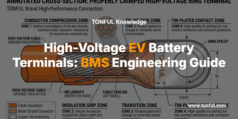
Crimp Quality and Reliability in HV Terminals
An improperly crimped EV battery terminal is a latent failure mode. At 200+ amps, even a 10% reduction in crimp cross-section area raises resistance enough to create a thermal hot spot.
TONFUL applies cross-section analysis (metallographic testing) and pull-force validation to 100% of HV terminal production lots:
- Crimp height tolerance: ±0.05 mm (monitored by force-displacement curves)
- Pull-off force: Minimum per UL 486A / USCAR-21 testing standards
- Contact resistance (mΩ): Measured at 100 A DC per USCAR-2 / USCAR-21 protocols
For a comprehensive reference on crimp validation, see our technical articles on crimp pull-force testing and crimp terminal quality control and safety testing standards.

Why OEMs and Tier-1 Suppliers Choose TONFUL
TONFUL Electric manufactures a complete range of automotive terminals and connectors from our ISO 9001 / IATF 16949-certified facilities in China. Our capabilities include:
- Custom wire harness assemblies designed for EV battery packs with application-specific terminal selection
- Full material traceability from copper rod to finished terminal, with tin-plated copper terminal compliance documentation
- In-house testing including tensile testing and metallographic analysis per IPC/WHMA-A-620 and IPC/WHMA-A-620 wire harness standards
- Tooling for both open-barrel and closed-barrel terminals supporting wire ranges from 0.5 mm² to 95 mm²
- Assorted kits for MRO and after-market distribution — see our terminal assortment boxes and crimping terminal organizer solutions
For sourcing guidance, our detailed article on importing electrical terminals from China covers logistics, quality audit checklists, and MOQ expectations.
Frequently Asked Questions
What makes EV battery terminals different from standard automotive terminals?
EV battery terminals must withstand voltages of 400–800 V DC (versus 12–48 V in conventional vehicles), requiring greater creepage/clearance distances, reinforced insulation, and plating systems rated for higher operating temperatures. They also undergo stricter qualification testing per UL 2580 and ISO 26262.
What is the best plating for high-voltage EV terminals?
Tin plating (3–8 µm) is the most cost-effective option for busbar connections. For safety-critical BMS signal pins, nickel-gold (Ni/Au) plating delivers the lowest and most stable contact resistance over the pack’s 15-year service life. See our full comparison of terminal plating: tin vs. silver vs. gold.
How do 800 V systems affect terminal selection?
At 800 V, minimum creepage distance doubles to 12.5 mm per IEC 60664-1. Terminal housings require thicker insulation walls, and partial discharge onset must exceed 2,400 V peak. However, current is halved at equivalent power, potentially allowing smaller conductor cross-sections.
What crimp quality standards apply to EV battery terminals?
Terminals must pass USCAR-21 pull-force and contact-resistance testing, metallographic cross-section analysis per IPC/WHMA-A-620, and environmental durability testing including thermal cycling (−40 °C to +150 °C) and salt spray exposure (≥ 500 h per ASTM B117).
Can TONFUL supply custom HV terminals for prototype and low-volume programs?
Yes. TONFUL supports high-mix, low-volume (HMLV) wire harness manufacturing with prototype tooling lead times as short as 2 weeks. Our engineering team works directly with OEM battery-pack designers to validate terminal specifications before mass production.
What wire gauge ranges do TONFUL HV terminals support?
TONFUL manufactures terminals for wire sizes from 22 AWG (0.34 mm²) for BMS sense lines up to 2/0 AWG (67.4 mm²) for pack main busbars. Refer to our AWG-to-metric conversion chart and terminal selection guide for detailed cross-referencing.
Ready to specify high-voltage terminals for your next EV battery program? Contact TONFUL Electric for engineering support, samples, and volume pricing.
