
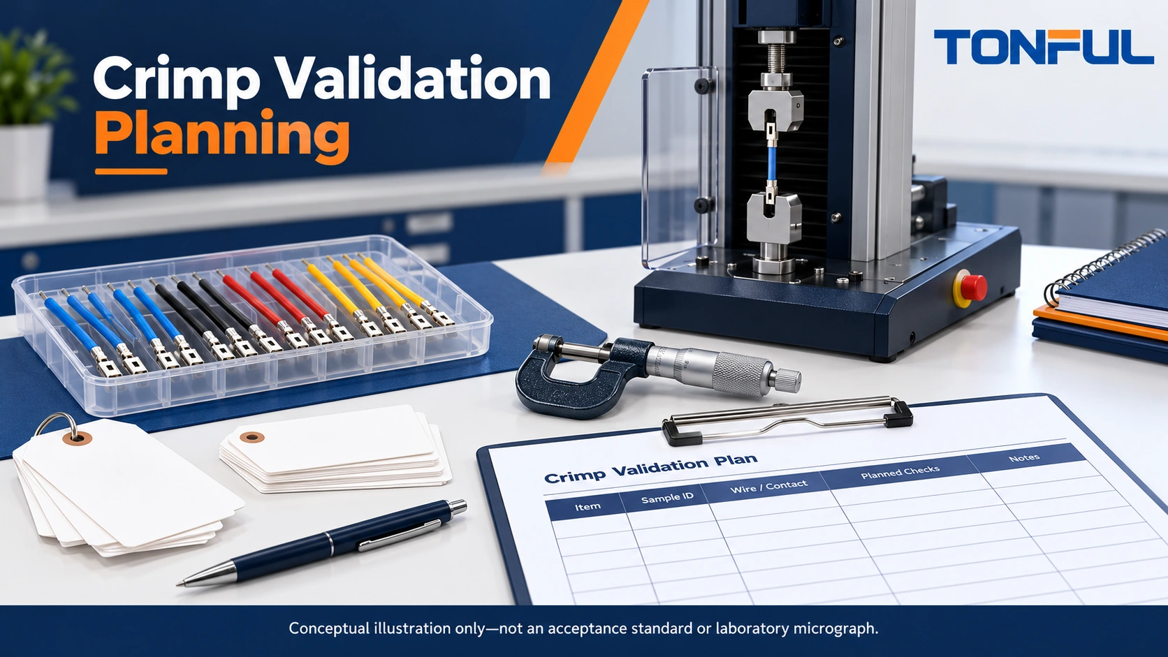
A crimp can survive a pull test and still leave questions about conductor damage, dimensional control or electrical performance. Crimp quality validation therefore combines evidence from the actual terminal, wire, tooling and process. No single photograph, force value or machine setting proves that every requirement has been met.
For harness buyers, the objective is an approved connection system with repeatable controls and traceable results. This guide explains what pull force, crimp height and section analysis can contribute, how to plan samples, and how to investigate conflicting evidence. Acceptance values must come from the applicable terminal specification, product drawing, customer requirement or approved qualification plan.
Establish the Connection System and Validation Plan
Identify more than nominal wire gauge
Record terminal part number and revision, material or plating requirements, wire size, conductor material, strand construction and insulation dimensions. Include seals and insulation-support features where they affect preparation or tooling. Wires with the same nominal gauge can differ in construction and handling; an approved setup should identify the combination it actually covers.
Record the tool, applicator or die, cavity, setup and relevant maintenance status. Confirm compatibility from the component application documents. Do not select a cavity only because the terminal fits into it, and do not substitute a generic force or height limit for the specified connection system.
The Molex Quality Crimp Handbook discusses crimp height and pull testing as parts of crimp-process evaluation. Use that manufacturer guidance for context, while the actual component application specification and agreed project criteria govern the combination being released.
Allocate samples before destructive work begins
Define sample quantity, production source and allocation by the approved plan. Identify whether specimens represent process extremes, wire variants, tooling changes or environmental conditions. State who approves the quantity and the rationale; there is no universal sample count that validates all terminal designs.
Allocate separate specimens for destructive pull tests and sections unless an authorized sequence calls for both on a defined sample. Retain unaltered references where useful. If aging is included, state which samples are measured initially and afterward, and which are reserved for teardown. A pulled specimen cannot automatically represent the untouched crimp geometry.
Define replacement-sample rules before execution. A genuine failure must remain in the report even when additional specimens are tested. Replacements may support investigation, but they must not silently improve the reported pass rate by removing failed samples.

Measure Crimp Height and Control the Setup
Use the specified feature and measurement method
Identify the conductor-crimp measurement location from the terminal application document. Use suitable measuring faces and an approved technique for the terminal geometry. Measuring across a flare, seam, insulation-support feature or distorted surface can report a dimension unrelated to the specified conductor-crimp height.
Record the gauge identity, resolution, accuracy, calibration and measurement result. Establish measurement-system suitability for the tolerance and operator method. A gauge with a fine displayed increment is not automatically accurate enough to support a narrow acceptance window.
Separate conductor-crimp dimensions from insulation support, seal support and overall terminal geometry. A conductor-height result cannot establish that the insulation has been supported without damage. Inspect relevant features individually, using their own source requirements.
Check preparation before adjusting tooling
Review strip length, insertion position, missing strands, birdcaging, insulation in the conductor area and terminal placement. An out-of-range result may involve the wrong material or measurement location, not merely an incorrect press adjustment. Preserve the first-piece evidence before changing the setup.
Check tooling wear, terminal feeding, alignment and contamination according to the equipment and application instructions. Make adjustments through the authorized setup method, then verify affected characteristics. Do not increase compression simply to improve a pull value if the resulting height or conductor condition becomes unacceptable.
Integrate setup controls with the wire harness manufacturing process. Define verification after applicable tool, material or program changes and after maintenance or restart. Trend required measurements within the approved control plan; do not confuse a collection of passing measurements with a demonstrated capable process.
Perform Pull Testing With a Defined Mechanical Boundary
Specify rate, grips and specimen condition
The approved method should state pull speed, loading direction, free wire length, grip arrangement and terminal support. Select equipment range and accuracy suitable for the expected force. Record conditioning or pre-treatment, including temperature and moisture where required by the plan.
Define whether insulation support must be made mechanically ineffective and how that preparation is performed. This depends on the governing method and connection system. Do not cut or alter the specimen arbitrarily: preparation can damage the conductor or change the boundary being evaluated.
Align the specimen so the intended axial load is applied without unintended bending or levering. Grips should resist slipping without creating a premature break at the grip. Use guards, eye protection and the equipment’s approved safety procedure for destructive loading; trained operators should not hold specimens by hand during the pull.
Record force and failure mode together
Capture the required force result and any force-displacement or time record specified by the plan. Describe where failure occurred: conductor fracture, strand pull-out, terminal separation, terminal deformation or grip-related event. Photograph preserved specimens with identity and orientation where the investigation requires it.
A wire break is not automatically proof of acceptance. The force, fracture location and applicable failure-mode rules still matter. Similarly, a terminal pull-off is not automatically a rejection without evaluating the governing method and threshold. Do not classify results from the failure description alone.
| Pull-test record | Required definition |
|---|---|
| Sample and combination | Terminal, wire, lot, tool and cavity |
| Preparation | Insulation-support treatment and specimen condition |
| Loading | Speed, direction, free length and grip arrangement |
| Equipment | Range, accuracy, calibration and fixture identity |
| Result | Required force value and preserved raw record |
| Failure mode | Separation or fracture location and specimen evidence |
| Decision | Acceptance document, result and reviewer |
For workmanship requirements, consult the IPC/WHMA-A-620 buyer guide and identify the contractual revision and class. Do not transplant a pull-speed or force table from a different standard, revision, wire material or terminal category.

Use Cross-Sections and Electrical Evidence for Remaining Questions
Prepare a traceable section, not a decorative comparison
Section analysis can expose internal geometry that external inspection cannot show. Its usefulness depends on where the specimen is cut and how the surface is prepared. Define the section location, cutting and mounting method, polishing or other preparation, observation conditions and applicable acceptance source.
Retain sample identity, terminal and wire combination, tool or cavity, measured height, calibrated scale, section plane and original image reference. Preparation damage can resemble a process defect, so the laboratory should distinguish artifacts from actual barrel or conductor features before drawing a conclusion.
Inspect the features required by the governing specification, such as conductor distribution, deformation, cracks or other defined conditions. Do not apply a universal void percentage or compaction target without an applicable source. One section plane also cannot establish every feature along the entire crimp length.
Do not let a mechanical pass replace an electrical requirement
If the project requires low resistance or loaded voltage drop, define the current, probe locations, temperature and acceptance source. A four-wire method minimizes current-lead effects, but the result includes every resistance between the Sense points. Record raw values, any approved correction and aged change where applicable.
The harness continuity testing guide explains why basic connectivity is not a complete low-resistance or load-performance qualification. Environmental testing should be included when the qualification plan, product specification or customer requires it, not simply because a test laboratory can perform it.
When results disagree, investigate the measurement boundary and specimen history. A high pull result with damaged strands may suggest excessive deformation or preparation damage; it does not identify the cause on its own. A correct measured height with poor pull performance may involve insertion, material or fixture issues. Confirm the mechanism before changing the process.
Link Findings to Production Control and Release Evidence
Contain, confirm and correct
For a valid failure, identify the affected setup and lot boundary. Preserve tool settings, material identities and specimens before adjustment or teardown. Consider work in progress and previously produced material where the evidence suggests a shared cause.
Use invalid-test rules only when the approved test was demonstrably not performed correctly, such as verified grip slippage outside the permitted method. Retain the original result and explanation. Rework, replacement specimens and retesting require authorization and cannot erase valid failures.
Permanent correction should address the confirmed cause: preparation, feeding, tooling condition, material mismatch, instruction ambiguity or design incompatibility. Update linked instructions and reaction plans, verify the corrected combination and check effectiveness over the approved follow-up scope. Avoid changing an acceptance threshold to accommodate an unexplained result.
Use a combined validation record
| Record field | Required entry |
|---|---|
| Configuration | Terminal, wire, tool, cavity, lots and revisions |
| Sample allocation | Quantity, variants, sequence and destructive use |
| Preparation | Strip, insertion and conditioning evidence |
| Height | Location, gauge, result and source limit |
| Pull | Method, speed, fixture, force and failure mode |
| Section | Plane, preparation, scale and original image reference |
| Electrical evidence | Current, probes, temperature, raw/corrected values |
| Acceptance source | Drawing, application specification or approved plan |
| Investigation | Initial failure, containment and invalid-test evidence |
| Disposition | Pass/fail, exceptions, reviewer and release scope |

Before approving routine production, separate qualification evidence from ongoing setup verification and production sampling. Agree on change triggers for wire construction, terminal source, tooling, process and test method. The custom harness sourcing guide helps buyers place these responsibilities in the supplier review.
Send your terminal and wire details, drawing, application conditions and required acceptance documents through TONFUL’s project enquiry channel. Request a proposed validation and production-control plan with open requirements identified. Confirm the available measurement and reporting scope before samples or production are authorized.