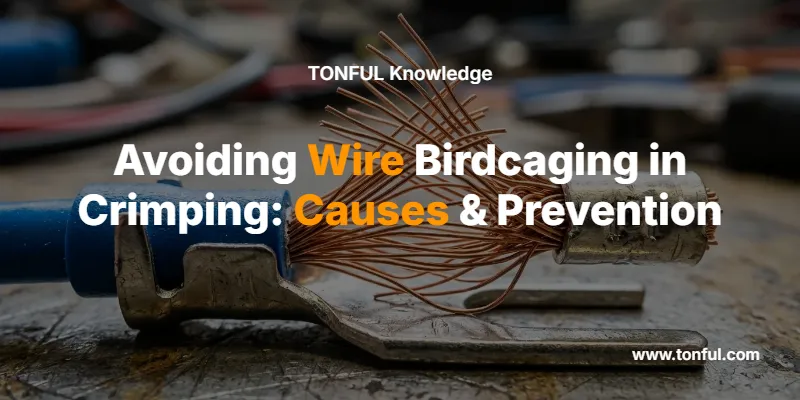
Wire birdcaging is one of the most destructive—and preventable—crimping defects in electrical manufacturing. When individual conductor strands splay outward between the insulation grip and the wire barrel of a crimp terminal, the resulting bulge resembles the wire frame of a birdcage. This failure mode increases electrical resistance, weakens pull-out strength, and can trigger field failures that cost OEMs and distributors thousands of dollars in warranty claims.
In this guide, TONFUL Electric’s engineering team explains the root causes of wire birdcaging, the correct tool setup procedures, and the wire stripping best practices that eliminate the defect at the source.
What Is Wire Birdcaging in Crimping?
Wire birdcaging—also called strand separation or strand flare—occurs when stranded wire conductor filaments spread radially outward in the transition zone between the insulation support and the conductor crimp barrel. The IPC/WHMA-A-620D standard classifies birdcaging as a Defect (Class 1, 2, and 3), meaning no acceptance level exists for this condition in any product class.
A proper crimp creates a gas-tight, cold-welded joint where the terminal barrel compresses every strand into intimate metallic contact. Wire birdcaging breaks this seal. Displaced strands reduce the effective cross-sectional area participating in the crimp, which leads to:
- Increased contact resistance — fewer strands carry current, generating localized heat
- Reduced pull-out force — failing USCAR-21 and UL pull-force minimums
- Accelerated corrosion — exposed bare copper invites oxidation in the separation zone
- Intermittent connections — vibration in automotive or industrial applications causes dropout

Root Causes of Wire Birdcaging
Understanding why wire birdcaging occurs is the first step toward eliminating it. In our experience manufacturing millions of terminals and connectors, these five factors account for over 95% of birdcaging defects:
1. Excessive Strip Length
When too much insulation is removed, the unsupported conductor span between the insulation edge and the terminal barrel becomes a buckling zone. During crimp compression, axial forces push strands outward in this unsupported gap.
2. Incomplete Wire Insertion
If the stripped conductor is not fully seated to the terminal’s wire stop, a gap remains between the barrel entrance and the conductor tip. Compression forces then displace strands into this void.
3. Incorrect Die Selection or Wear
Oversized or worn crimping dies fail to apply uniform radial compression. Strand containment is lost, and individual filaments escape laterally. Proper crimping tool maintenance and calibration prevents this.
4. Wire Gauge–Terminal Mismatch
Using a conductor that is too small for the terminal barrel leaves excess clearance, allowing strands to rearrange under compression rather than consolidating into a gas-tight mass.
5. Strand Damage During Stripping
Nicked, cut, or severed strands during the insulation removal process create weak points. Damaged strands buckle preferentially, initiating wire birdcaging even when other parameters are correct. Avoiding common crimping mistakes begins at the stripping stage.
| Root Cause | Mechanism | Frequency | Severity |
|---|---|---|---|
| Excessive strip length | Unsupported conductor span buckles under axial load | Very Common | High |
| Incomplete wire insertion | Gap between conductor and wire stop allows strand escape | Common | High |
| Incorrect or worn die | Non-uniform radial compression; strand containment failure | Moderate | Critical |
| Wire gauge mismatch | Excess barrel clearance permits strand rearrangement | Moderate | Medium |
| Strand damage from stripping | Nicked strands buckle preferentially under crimp force | Common | Medium–High |
Proper Crimping Tool Setup to Prevent Wire Birdcaging
Selecting and setting up the right crimping tools is the most impactful step you can take against wire birdcaging.
Tool Selection by Application
| Crimp Type | Recommended Tool | Die Profile | AWG Range | Birdcaging Risk if Mismatched |
|---|---|---|---|---|
| Open-barrel terminals | Ratcheting W-crimp tool | W / M profile | 22–10 AWG | High — strand escape at barrel edges |
| Insulated terminals (nylon/PVC) | Color-coded ratchet crimper | Oval indent | 22–10 AWG | Moderate — insulation grip zone failure |
| Ferrule end terminals | Self-adjusting ferrule crimper | Trapezoidal / hexagonal | 28–4 AWG | Low — full circumferential containment |
| Sealed heat-shrink terminals | Dual-indent ratchet crimper | Dot / ring indent | 22–10 AWG | Moderate — if strip length exceeds barrel |
Die Matching and Calibration
Every terminal manufacturer specifies a crimp height (measured in mm from the bottom of the compressed barrel to the top). At TONFUL, our wire terminals ship with recommended crimp height specifications per AWG size. For example:
- 16 AWG insulated ring terminal: Target crimp height 3.50 ± 0.10 mm
- 14 AWG open-barrel tab: Target crimp height 2.85 ± 0.08 mm
- 22 AWG ferrule terminal: Target crimp height 1.60 ± 0.05 mm
Use a crimp height micrometer or go/no-go gauge to verify. An out-of-spec crimp height is the number-one predictor of wire birdcaging in production environments.
Ratchet Mechanism Check
A calibrated ratcheting crimper must complete its full stroke before releasing. If the ratchet disengages prematurely or requires excessive force override, the tool needs servicing. Incomplete strokes leave the barrel partially formed, and the uncompressed region becomes the birdcage initiation site.
Correct Wire Stripping Techniques
Proper wire stripping is what should be done to ensure a good crimp connection before the crimping tool ever closes. The strip length must match the terminal barrel depth so the conductor fills the barrel completely—with approximately 0.5–1.0 mm (1/32″) of conductor visible past the barrel end as a visual verification of full insertion.
Strip Length by Terminal Type

| Terminal Type | Typical Strip Length | Verification Method | Birdcage Risk Factor |
|---|---|---|---|
| Ring terminal (16–14 AWG) | 5.5–6.5 mm | Conductor visible 0.5 mm past barrel | High if over-stripped |
| Butt splice (16–14 AWG) | 7.0–8.0 mm per side | Conductor centered, visible at inspection window | Moderate |
| Ferrule (16–14 AWG) | Equal to metal sleeve depth | Flush with ferrule tip, no protrusion | Low |
| Open-barrel tab (16–14 AWG) | Barrel depth + 0.5 mm | Conductor visible past wire stop | High if under-inserted |
Stripping Best Practices
- Use calibrated stripping tools — Set the blade depth to cut through insulation only, never nicking conductor strands. Automatic strippers with adjustable stops provide the most consistent results across AWG 22–10.
- Verify strand integrity — After stripping, inspect the conductor bundle visually. Shiny nicks, severed strands left in the removed insulation sleeve, or a visible reduction in strand count all indicate damage. Discard and re-strip.
- Maintain strand lay — Do not over-twist or fan out strands before insertion. A gentle twist (less than one full revolution) maintains the natural lay of the conductor bundle and ensures uniform insertion into the barrel.
- Match strip length to the barrel — Measure the terminal’s wire barrel depth with calipers before your first crimp of a new production lot. Strip lengths that worked for a previous supplier’s terminal may not apply to a new part number.
Learn more about correct technique in our complete guide on how to properly crimp electrical wires.
Prevention Best Practices and Quality Control
In-Process Inspection
Catching wire birdcaging requires visual and mechanical checks at the crimp station:
- Visual inspection (100%): Every crimp should be inspected for strand protrusion, barrel symmetry, and insulation grip engagement. Wire birdcaging is visible to the trained eye without magnification.
- Crimp height measurement (SPC sampling): Use statistical process control with a minimum sample of 5 pieces per setup and hourly intervals per IPC/WHMA-A-620D.
- Pull-force testing (destructive sampling): Perform pull-out force tests per UL 486A-486B or USCAR-21 requirements. A birdcaged crimp typically fails at 40–60% of the specification minimum.
Cross-Section Analysis
For critical applications (automotive, aerospace, medical), periodic crimp cross-section analysis reveals internal wire birdcaging that may not be visible externally. The polished cross-section shows strand compaction ratio, void percentage, and any internal strand displacement.

Applicable Industry Standards
| Standard | Scope | Wire Birdcaging Relevance |
|---|---|---|
| IPC/WHMA-A-620D | Wire harness workmanship | Classifies birdcaging as Defect in all product classes |
| USCAR-21 | Automotive terminal performance | Pull-force and resistance testing reveals birdcage-induced failures |
| UL 486A-486B | Wire connector safety | Mechanical and electrical testing for crimped connections |
| SAE/USCAR-2 | Automotive connector performance | Environmental and vibration testing standards |
For guidance on selecting the right connector type and understanding insulation options, see our comparison of insulated vs. non-insulated wire connectors.
Why Terminal Quality Matters
Even with perfect tool setup and stripping technique, low-quality terminals with inconsistent barrel dimensions, poor plating adhesion, or incorrect copper alloy hardness can promote wire birdcaging. The barrel material must have sufficient ductility to flow around the conductor strands during compression, yet enough spring-back resistance to maintain gas-tight contact pressure.
At TONFUL, every production lot of crimp terminals undergoes dimensional inspection, plating thickness verification, and material hardness testing before shipment. This quality-first approach is why engineers trust TONFUL terminals for applications where crimped connections must perform as reliably as soldered joints.
Need help selecting the right terminals for your application? Our engineering team can help you choose the right wire connectors to eliminate birdcaging from your production line.
Frequently Asked Questions
What is wire birdcaging in crimping?
Wire birdcaging is a crimping defect where individual strands of a stranded conductor splay outward between the insulation grip and the conductor barrel of a crimp terminal. The bulging strands resemble a birdcage structure. It is classified as a Defect under IPC/WHMA-A-620D for all product classes.
What causes wire birdcaging?
The most common causes are excessive wire strip length, incomplete conductor insertion into the terminal barrel, incorrect crimping die selection, wire gauge–terminal size mismatch, and strand damage during insulation stripping.
How do I prevent birdcaging when crimping?
Strip wire to the exact barrel depth (plus 0.5 mm for visual verification), fully insert the conductor to the terminal wire stop, use the correct die size for your terminal, verify crimp height with a micrometer, and inspect every crimp for strand protrusion.
Can wire birdcaging be repaired?
No. A birdcaged crimp must be cut off and re-crimped with a new terminal. Attempting to re-crimp over a birdcaged connection traps displaced strands outside the compression zone and worsens the defect.
What strip length prevents birdcaging?
The strip length should match the terminal barrel depth plus approximately 0.5–1.0 mm. For typical 16–14 AWG ring terminals, this is 5.5–6.5 mm. Always verify against the terminal manufacturer’s specification sheet.
Does wire birdcaging affect electrical performance?
Yes. Birdcaging reduces the number of strands participating in the gas-tight crimp zone, increasing contact resistance and causing localized heating. In pull-force testing, birdcaged crimps typically fail at 40–60% of the rated minimum, making the connection both electrically and mechanically unreliable.
