
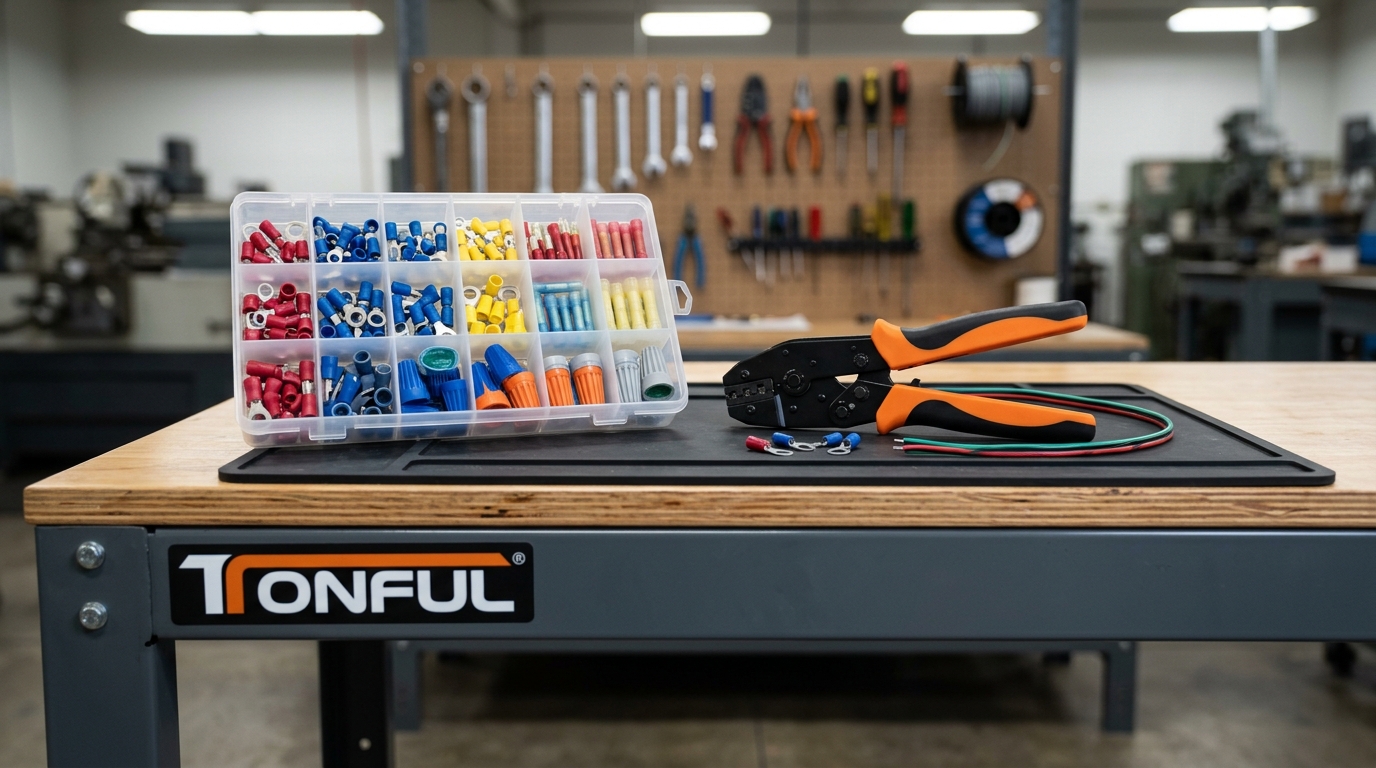
Selecting the correct wire connector is one of the most consequential decisions in any electrical assembly. A connector that is undersized, improperly rated, or mismatched to its environment can become a hidden point of failure—generating heat, increasing resistance, and in the worst cases, causing thermal events that destroy equipment or trigger fires. For procurement teams, engineers, and installers working across automotive, marine, industrial, and residential applications, the question is not simply “which connector fits this wire,” but “which connector will remain reliable under the full range of operating conditions over the product’s service life.”
This guide walks through the engineering criteria that govern wire connector selection—wire gauge and current capacity, environmental sealing, termination method, compliance standards, and mechanical reliability—so you can specify with confidence. For a broader survey of connector categories, see our complete guide to types of wire connectors, and for application context, our overview of what wire connectors are used for.

The Five Selection Factors That Actually Matter
Wire connector selection collapses into five engineering variables. Get these right and the connector will perform; miss any one and the connection becomes a liability.
| Selection Factor | What It Governs | Key Specification to Verify |
|---|---|---|
| Wire gauge (AWG) range | Mechanical grip, current path cross-section | Connector’s listed min–max AWG; color code per DIN/UL |
| Current & voltage rating | Thermal rise under load, dielectric integrity | Ampere rating at rated voltage (e.g., 600 V) |
| Environmental rating | Moisture, dust, chemical, UV resistance | IP code (IEC 60529); UL 486D for direct burial |
| Termination method | Joint integrity, reworkability, gas-tight seal | Crimp, solder, IDC, screw, or push-in |
| Compliance & standards | Code acceptance, third-party safety validation | UL 486A/B/C/D, RoHS, REACH, IATF 16949 |
These factors are interdependent. A connector with the correct AWG range but an inadequate IP rating will corrode in a marine harness; a waterproof connector with the wrong crimp profile will fail pull-force testing regardless of its sealing. For guidance on matching connector insulation to your environment, see our comparison of insulated vs. non-insulated wire connectors.
Wire Connector Types: Comparison at a Glance
Different termination methods suit different constraints—permanence, vibration, serviceability, and tooling availability all factor in. The table below compares the dominant wire connector families used in B2B electrical assemblies.
| Connector Type | Typical AWG Range | Best Application | Key Advantage | Main Limitation |
|---|---|---|---|---|
| Crimp ring/space terminals | 22–10 AWG | Grounding, panel-mounted equipment | Vibration-resistant, removable | Requires calibrated crimp tool |
| Butt splices | 26–10 AWG | In-line wire-to-wire joins | Compact, fast installation | Permanent; not reworkable |
| Heat-shrink terminals | 22–10 AWG | Marine, automotive, outdoor | Adhesive-lined environmental seal | Requires heat gun; slower install |
| Waterproof wire nuts | 22–10 AWG | Landscape lighting, irrigation | Gel seal blocks moisture | Single-use; size-specific |
| Push-in / lever connectors | 24–12 AWG | Residential junction boxes | Tool-free, reusable | Lower current ceiling |
| Solder-seal butt connectors | 26–8 AWG | Marine, submersible repairs | Solder + adhesive seal in one step | Needs controlled heat application |
| PCB pin/wafer headers | 28–18 AWG | Wire-to-board, electronics | High-density, automated assembly | Not field-serviceable without depinning |
For high-current DC power links, bolted copper lugs outperform crimp-only solutions. For automotive and marine harnesses, explore our heat-shrink terminals and automotive electrical connectors. When joining dissimilar wire sizes, step-down butt connectors maintain a controlled current path without strand trimming.

Matching Wire Gauge to Current Load
The American Wire Gauge system runs inversely—higher gauge numbers mean thinner conductors. A connector rated for 22–18 AWG cannot safely carry the current of a 10 AWG circuit, and forcing a 10 AWG wire into a small barrel requires trimming strands, which reduces ampacity and creates a localized heat bottleneck. Conversely, an oversized connector cannot achieve the uniform crimp pressure needed for a gas-tight seal, leaving the joint vulnerable to oxidation.
Insulated crimp terminals follow a standardized color code recognized across UL and DIN frameworks: red for 22–18 AWG, blue for 16–14 AWG, yellow for 12–10 AWG. This coding allows rapid field verification. Our crimp terminal color code chart and AWG-to-metric conversion guide provide full lookup tables for cross-referencing imperial and metric conductor sizes.
| AWG | Approx. Ampacity (chassis, copper) | Typical Connector Color | Common Application |
|---|---|---|---|
| 22–18 AWG | 7–14 A | Red | Signal, low-voltage lighting, sensor leads |
| 16–14 AWG | 18–25 A | Blue | Automotive lighting, small appliances |
| 12–10 AWG | 30–40 A | Yellow | Battery feeds, main power distribution |
| 8–6 AWG | 55–75 A | Uninsulated lug | Starter motors, inverters, EV packs |
| 4–1/0 AWG | 95–150 A | Compression lug | Heavy-duty truck, solar busbars |
Ampacity assumes copper conductors at chassis ambient; derate by 15–20% for enclosed harnesses or continuous duty. Always verify against the connector manufacturer’s published rating rather than the wire’s standalone ampacity—the connector is typically the thermal bottleneck.
Environmental Sealing: IP Ratings and UL 486D
Environmental exposure is the single most common cause of premature connector failure. A connection that is electrically sound on the bench can fail within months if moisture ingress corrodes the contact interface. Two rating systems govern environmental protection, and they answer different questions.
IP ratings (IEC 60529) classify ingress protection against solids and liquids. IP67 means dust-tight and protected against temporary immersion (1 m, 30 min); IP68 means protected against continuous immersion under specified conditions. UL 486D is a material and sealing standard specifically for sealed wire connector systems used in wet locations and direct burial. A connector can carry an IP68 rating yet still lack the UL 486D listing required for below-grade splices, because IP tests short-term water entry while UL 486D validates long-term soil-contact material stability. For any underground splice, require both certifications.
For a deeper comparison, see our guides on IP67 vs. IP68 waterproof wire nuts and how to choose waterproof wire connectors. Marine applications have additional corrosion-prevention requirements covered in our marine wiring corrosion prevention guide.
| Environment | Minimum Sealing | Recommended Standard | Typical Connector |
|---|---|---|---|
| Indoor junction box (dry) | None required | UL 486A/B | Standard wire nut, push-in |
| Damp / condensing | IP54 | UL 486C | Heat-shrink butt splice |
| Outdoor, rain-exposed | IP67 | UL 486D | Gel-filled waterproof wire nut |
| Direct burial / submersible | IP68 + UL 486D | UL 486D | Solder-seal, sealed splice kit |
| Engine bay (heat + vibration) | IP67, high-temp | UL 486A/B + OEM spec | Nylon-insulated crimp, heat-shrink |
Standards and Compliance: What the Certifications Mean
Third-party certifications are not marketing decoration—they define the test conditions a connector survived, and therefore the installations where it is code-compliant. The UL 486 family is the backbone for North American wire connector safety:
- UL 486A/B — General wire connectors and soldering lugs for copper/aluminum conductors; covers mechanical strength, dielectric withstand, and pull-out force.
- UL 486C — Splicing wire connectors (butt splices, tap connectors).
- UL 486D — Sealed wire connector systems for wet locations and direct burial.
- UL 486F — Ferrules evaluated for use with 486A/B-listed connectors.
For the full breakdown of how these standards differ and which applies to your installation, see our UL 486 vs. UL 310 comparison guide. Automotive and industrial buyers should also verify IATF 16949 manufacturing certification and RoHS/REACH material compliance.

Termination Method: Crimp vs. Solder vs. Push-In
The termination method determines joint reliability, serviceability, and tooling cost. Crimping is the industry standard for vibration-prone applications—automotive, marine, aerospace—because a properly executed crimp creates a cold-welded, gas-tight joint that resists fatigue better than solder, which can crystallize under cyclic stress. The solder vs. crimp debate is application-dependent: solder excels for static, low-vibration PCB work; crimp dominates in vehicular and industrial harnesses.
Push-in and lever connectors prioritize installation speed and reworkability but carry lower current ceilings and are generally limited to residential and light-commercial wiring. IDC (insulation displacement) connectors, common in telecom and automotive quick-splices, eliminate stripping but require precise wire OD matching. Regardless of method, a properly calibrated crimping tool is non-negotiable—our how to properly crimp electrical wires and how to crimp heat-shrink terminals correctly guides cover the procedure in depth. For tool selection, see how to choose the correct tool.
| Method | Vibration Resistance | Reworkable | Tooling Cost | Best Use Case |
|---|---|---|---|---|
| Crimp (ratcheting) | Excellent | No | Medium | Automotive, marine, industrial |
| Solder | Moderate (fatigue risk) | No | Low | Static PCB, prototype |
| Push-in / lever | Good | Yes | Low | Residential junction boxes |
| IDC / quick-splice | Fair | No | Low | Tap-in signal, non-critical |
| Screw terminal | Good | Yes | Low | Panel-mounted equipment |
A Step-by-Step Selection Methodology
When the variables interact, a disciplined sequence prevents specification errors. Work through these five steps in order—each narrows the candidate pool before the next factor is applied.
- Define the electrical load. Identify the circuit’s maximum continuous current and voltage. Select a connector rated at least 125% of the continuous load to provide thermal headroom.
- Confirm the wire gauge. Cross-reference the conductor’s AWG and stranding against the connector’s listed range. Never trim strands to force a fit.
- Characterize the environment. Determine IP and UL 486 requirements from the installation location. Underground, engine bay, and outdoor exposures each demand specific sealing.
- Choose the termination method. Match the method to vibration profile, serviceability needs, and available tooling. Default to crimp for vehicular and industrial work.
- Verify compliance. Confirm the connector carries the applicable UL listing, and for automotive applications, that the manufacturer holds IATF 16949 certification.
For identifying quality at the component level—plating thickness, barrel seam integrity, insulation uniformity—our guide on how to identify the quality of a crimp terminal provides inspection criteria you can apply at incoming QC.

Common Selection Mistakes and How to Avoid Them
Most field failures trace back to a handful of recurring mistakes. Recognizing them at specification time eliminates the majority of warranty and rework costs.
- Undersizing for current headroom. Selecting a connector rated exactly at the load current leaves no margin for inrush, ambient rise, or aging. Derate by 25%.
- Ignoring stranding type. Fine-strand and ultra-fine-strand wire requires ferrules or specific crimp profiles; standard terminals designed for solid or coarse-strand conductors will not grip correctly. Use cord-end terminals for ferrule applications.
- Mismatching tooling to terminal. Each terminal profile (F-crimp, O-crimp, open-barrel) requires a matching die. A generic pliers crimp fails pull-force testing. See our understanding crimp dies guide.
- Specifying IP without UL 486D for burial. An IP68 connector without a UL 486D listing is not code-compliant for underground splices.
- Skipping pull-force validation. Production crimps should be sample-tested to the connector’s tensile specification. Our crimp pull-force testing guide covers the procedure.

Short FAQ
Q: How do I know what size wire connector to use? Match the connector’s listed AWG range to your conductor gauge and verify the current rating exceeds your continuous load by at least 25%. Use the color code (red/blue/yellow) for insulated crimp terminals as a quick field check. See our AWG-to-metric conversion chart for full sizing.
Q: Are crimped connections as reliable as soldered ones? For vibration-prone applications—automotive, marine, aerospace—properly crimped connections outperform soldered joints, which can fatigue-crack under cyclic stress. Solder remains preferred for static PCB work. See our solder vs. crimp analysis.
Q: What’s the difference between IP67 and IP68 wire connectors? IP67 protects against temporary immersion (1 m, 30 min); IP68 protects against continuous immersion under specified depth and duration. Neither automatically qualifies a connector for direct burial—require a UL 486D listing for underground splices. Compare ratings in our IP67 vs. IP68 guide.
Q: Can I reuse waterproof wire nuts? No. Waterproof wire nuts rely on a gel seal that deforms on first installation; removal breaks the seal integrity. They are single-use components. See our waterproof wire connector product page for sealed alternatives.
Q: Which standard applies to outdoor wire connectors? UL 486D governs sealed wire connector systems for wet locations and direct burial. UL 486A/B covers general indoor connectors. Cross-reference both in our UL 486 vs. UL 310 guide.
Specifying With Confidence
Choosing the right wire connector is an engineering decision driven by five quantifiable factors—wire gauge, current rating, environment, termination method, and compliance—each of which narrows the candidate field until the correct part is self-evident. The cost of getting it wrong is measured not in connector unit price but in field failures, warranty claims, and safety liability. TONFUL Electric manufactures a full range of UL-listed, IATF-certified wire connectors—from waterproof wire nuts and heat-shrink terminals to automotive electrical connectors and custom wire harness assemblies—with engineering support to validate your specification before it reaches production. When the selection is driven by data rather than habit, the connection holds for the life of the product.