A well-engineered e-bike wire harness is the circulatory system of every electric bicycle—routing power from a high-voltage lithium battery pack through the controller and out to the motor while simultaneously carrying low-level signals for throttle, brakes, display, and sensors. As e-bike platforms scale from 250 W city commuters to 3 000 W+ cargo and off-road machines, the demands placed on connectors, conductors, and protection systems multiply. This guide provides OEM engineers and procurement teams with the technical framework for selecting connectors and wire gauges that ensure safety, minimize voltage drop, and withstand real-world environmental stress.

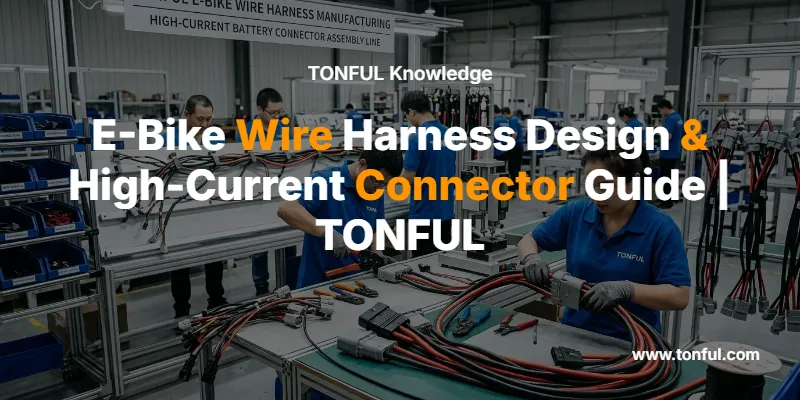
Image 1 Generation Instructions (Photorealistic): Industrial photography of a TONFUL e-bike wire harness assembly line. Show workers at a well-lit workstation crimping high-current XT90 connectors onto thick silicone battery cables. TONFUL logo should be prominently visible on a wall banner behind the workstation and embroidered on worker uniforms. Include visible crimping tools, wire spools, and a quality inspection station. Lighting: bright, even industrial LED overhead. Camera angle: slightly elevated 3/4 view. Style: editorial industrial photography, shallow depth of field on the crimping action.
Understanding E-Bike Wire Harness Architecture
An e-bike wire harness consolidates two fundamentally different circuit classes into a single routed loom:
- Power circuits — Battery-to-controller and controller-to-motor phase wires carrying 20–100 A at 36–72 V DC.
- Signal circuits — Throttle, hall sensor, PAS, brake lever, display communication, and lighting wires carrying ≤2 A at 5–12 V.
The design challenge lies in co-routing these circuits without electromagnetic interference (EMI) from high-current switching affecting sensitive hall or communication signals. Best practice separates power and signal bundles by a minimum of 25 mm within the harness trunk, using fleece or vinyl harness tape for abrasion and noise isolation.
A robust custom wire harness assembly integrates strain relief at every connector interface, maintains consistent bend radii, and specifies materials rated for the thermal environment of the frame-mounted controller compartment—often reaching 85 °C during sustained hill climbs.
Connector Selection for High-Current Battery Packs
Selecting the correct battery discharge connector is the single most critical decision in e-bike wire harness design. An under-rated connector introduces contact resistance that generates heat, causes voltage sag under load, and can ultimately melt or arc—creating a fire hazard in proximity to lithium cells.

Image 2 Generation Instructions (Technical Diagram): Clean, engineering-style cutaway illustration of an XT90 connector cross-section. Label the following parts with leader lines: gold-plated copper-alloy bullet pin (4.5 mm diameter), high-temperature nylon 66 housing, wire solder/crimp cup, anti-spark resistor (for XT90-S variant), and mating friction surface. Show red arrows indicating current flow direction through the contact interface. TONFUL logo positioned in the lower-right corner. Background: light grey technical grid. Style: vector-quality annotated engineering illustration.
Connector Types Comparison Table
| Parameter | XT60 | XT90 | Anderson PP45 | Higo L1019 |
|---|---|---|---|---|
| Continuous Current | 60 A | 90 A | 45 A | 45 A |
| Burst Current | 75 A | 120 A | 55 A | 60 A |
| Voltage Rating | 500 V | 500 V | 600 V | 48 V DC / 60 V AC |
| Contact Diameter | 3.5 mm | 4.5 mm | Flat blade | 2.0 mm |
| Housing Material | Nylon PA | Nylon PA | Polycarbonate | PBT |
| Waterproof Rating | None (IP20) | None (IP20) | None (IP20) | IP67 |
| Anti-Spark Option | XT60-S | XT90-S | No | N/A |
| Mating Cycles | 1 000+ | 1 000+ | 5 000+ | 3 000+ |
| Best Application | 250–750 W e-bikes | 1 000–3 000 W e-bikes | DIY / modular builds | OEM integrated systems |
Key selection criteria:
- Derate by 25–30 % — A 48 V / 1 000 W system draws ~21 A continuous but peaks at 40–60 A during acceleration. Select connectors with continuous ratings 1.5× your peak current.
- Anti-spark variants — XT60-S and XT90-S incorporate a pre-charge resistor contact that limits inrush current, protecting MOSFETs and capacitors in the controller.
- Waterproof requirements — For OEM consumer e-bikes ridden in all weather, overmolded Higo or Julet connectors with IP67 ratings eliminate field failures from moisture ingress.
For further details on terminal material science and plating, see our technical guide on automotive terminal plating: tin vs. silver vs. gold.
Wire Gauge Selection for E-Bike Power Circuits
Wire gauge directly governs voltage drop, thermal performance, and harness flexibility. The table below maps common e-bike power levels to recommended AWG sizing for battery-to-controller runs under 1 meter.

Image 3 Generation Instructions (Technical Diagram): Full-system wiring schematic of an e-bike electrical architecture drawn in a clean technical style. Show: 48 V battery pack (with BMS internal view) connected via XT90 connector and 10 AWG red/black wire to the motor controller. Controller outputs three 12 AWG phase wires (labeled U/V/W) through bullet connectors to hub motor. Separate signal branch shows 24 AWG wires for throttle, hall sensors, and display via JST-SM connectors. Annotate current values at each branch (e.g., “25 A continuous,” “≤0.5 A signal”). TONFUL logo at top-center header. Style: professional electrical schematic with color-coded wires on white background.
Wire Gauge Selection Chart
| System Power | System Voltage | Continuous Current | Recommended AWG | Max Cable Run | Voltage Drop (1 m) |
|---|---|---|---|---|---|
| 250 W | 36 V | 7 A | 14 AWG | 1.5 m | 0.18 V (0.5 %) |
| 500 W | 48 V | 10–12 A | 12 AWG | 1.5 m | 0.16 V (0.3 %) |
| 750 W | 48 V | 16 A | 12 AWG | 1.2 m | 0.21 V (0.4 %) |
| 1 000 W | 48 V | 21 A | 10 AWG | 1.5 m | 0.13 V (0.3 %) |
| 1 500 W | 52 V | 29 A | 10 AWG | 1.0 m | 0.19 V (0.4 %) |
| 3 000 W | 72 V | 42 A | 8 AWG | 1.5 m | 0.13 V (0.2 %) |
Engineering notes:
- Always use stranded copper conductors—solid wire fatigue-cracks under vibration.
- Silicone insulation (rated to 200 °C) outperforms PVC (rated to 80 °C) for routing near controllers and motor housings.
- For systems above 1 000 W, specify 10 AWG minimum regardless of calculated current to provide thermal headroom during sustained hill climbs and regenerative braking surges.
Refer to our wire AWG and insulation selection guide for detailed ampacity tables including temperature derating factors.
Waterproofing and Environmental Protection
Consumer e-bikes encounter rain, road splash, pressure-washing, and condensation from temperature cycling. Every exposed connector joint is a potential failure point.

Image 4 Generation Instructions (Photorealistic): Close-up industrial product photograph of XT60 (yellow, smaller) and XT90 (yellow, larger) connectors placed side-by-side on a stainless steel workbench surface. A digital caliper measures the XT90 housing width. Background shows blurred soldering station and TONFUL-branded heat shrink tubing spools. A TONFUL logo sticker is visible on the equipment in the background. Lighting: controlled studio-style with soft shadows. Camera: macro lens, f/4, sharp detail on connector surfaces. Style: clean product/industrial photography.
IP Rating Requirements by Application
| E-Bike Category | Minimum IP Rating | Connector Strategy |
|---|---|---|
| Urban commuter | IP54 | Sealed overmolded Higo/Julet connectors |
| All-weather commuter | IP65 | IP65 Higo + additional heat shrink sealing |
| Off-road / MTB | IP67 | Fully sealed IP67 + conformal-coated PCB |
| Cargo / delivery fleet | IP67–IP68 | IP68 rated connectors + potted controller |
| E-bike with removable battery | IP65 (connector) | Spring-loaded dust cap + gold-plated contacts |
Achieving IP67 or higher requires three layers of protection:
- O-ring seals at the connector mating interface
- Cable glands or overmolded strain relief at wire entry points
- Adhesive-lined heat shrink tubing at any splice or branch point within the harness

Image 5 Generation Instructions (Technical Diagram): Annotated cross-section illustration of an IP67 waterproof circular connector assembly. Show and label: outer threaded coupling nut, primary O-ring seal (between male and female housing), secondary cable entry grommet seal, gold-plated pin contacts, silicone gasket, and strain-relief collet. Use arrows pointing to each sealing element with descriptive labels. Color-code the sealing zones in blue overlay. TONFUL logo in the upper-left corner. Style: clean technical cutaway with semi-transparent housing walls, white background.
For guidance on selecting between IP67 and IP68 ratings for vehicles operating in extreme environments, see our article on IP67 vs. IP68 waterproof ratings for off-road vehicles.
Safety Standards and Testing
A professionally designed e-bike wire harness must satisfy multiple safety and quality benchmarks:
- IPC/WHMA-A-620 — Workmanship standard for cable and wire harness assemblies, defining crimp quality, solder joints, and cable dressing criteria. See our IPC/WHMA-A-620 standard guide.
- UL 2849 — Specific to e-bike electrical systems, covering insulation, overcurrent protection, and connector integrity.
- EN 15194 (EPAC) — European standard for electrically power-assisted cycles addressing electrical safety.
- Crimp pull-force testing — Validates mechanical retention of crimped terminals per crimp pull force testing standards.
Critical Test Parameters
| Test | Standard/Method | Pass Criteria |
|---|---|---|
| Crimp tensile | IPC-620 Table 10-1 | ≥ 80 % of wire breaking strength |
| Contact resistance | MIL-DTL-39029 | ≤ 5 mΩ per contact |
| Insulation resistance | IEC 60512 | ≥ 100 MΩ at 500 V DC |
| Temperature cycling | -40 °C to +125 °C (100 cycles) | No cracking, no resistance increase > 10 % |
| Salt spray | ASTM B117, 96 h | No functional degradation |
| Vibration | IEC 60068-2-6, 10–500 Hz | No intermittent open circuits |
TONFUL Electric applies wire harness continuity testing and 100 % pull-force validation on every high-current connection during production.
Design Best Practices for OEM Integration
When specifying an e-bike wire harness for volume manufacturing, consider these critical factors:
Connector standardization — Minimize the number of unique connector families. A well-designed system uses XT90 for battery discharge, bullet connectors for motor phase wires, and a single waterproof multi-pin connector (e.g., Higo 8-pin) for all signal circuits.
Strain relief at every interface — Frame vibration and rider-induced flex cycles cause wire fatigue at connector entry points. Overmolded boots or heat shrink tubing provide mechanical decoupling.
Harness protection — Route the harness within frame tubes where possible. External sections require split loom, braided sleeving, or wire harness protection methods appropriate to the abrasion and thermal environment.
Fusing — Always include an appropriately rated automotive blade fuse or equivalent inline fuse on the battery positive lead. A 48 V / 25 A system typically uses a 30 A blade fuse to protect against short circuits.
BOM optimization — Working with a single-source manufacturer like TONFUL for connectors, terminals, heat shrink, and cable ties simplifies procurement, reduces minimum order quantities, and ensures material compatibility. See our guide on wire harness assembly BOM optimization.
Why Partner with TONFUL for E-Bike Wire Harness Components
TONFUL Electric provides a complete ecosystem of components for e-bike wire harness manufacturing:
- Custom wire harness assemblies built to IPC-620 Class 2/3
- Heat shrink terminals for sealed, vibration-resistant connections
- Waterproof wire connectors rated IP67–IP68
- Automotive electrical connectors and terminals
- Electrical tools including professional crimpers calibrated for micro-ohm consistency
Our wire harness manufacturing process integrates automated cutting and stripping, precision crimping with 100 % force monitoring, and final continuity/hipot testing on every assembly.
Frequently Asked Questions
What wire gauge should I use for a 48 V 1000 W e-bike wire harness?
A 48 V / 1 000 W system draws approximately 21 A continuous with peak surges up to 40–60 A during acceleration. Specify 10 AWG stranded copper with silicone insulation for the battery-to-controller connection. This provides adequate thermal headroom and limits voltage drop to under 0.4 % per meter of cable run.
Can I use XT60 connectors on a 1500 W e-bike?
While XT60 connectors are rated for 60 A continuous, a 1 500 W / 52 V system draws ~29 A continuous with peaks potentially exceeding 50 A. The XT60 would operate near its continuous limit during sustained draws. We recommend XT90 connectors for any system above 750 W to maintain a 2× safety margin and minimize resistive heating at the contact interface.
How do I waterproof non-sealed connectors in an e-bike wire harness?
For retrofit waterproofing: apply adhesive-lined dual-wall heat shrink tubing over the mated connector pair, ensuring the adhesive melt flows into all gaps. For production builds, specify overmolded waterproof connectors (IP67 minimum) from the outset—field-applied waterproofing adds labor cost and introduces reliability risk compared to factory-sealed solutions. Learn more in our waterproof wire connector guide.
What is the difference between XT90 and XT90-S anti-spark connectors?
The XT90-S variant includes a small pre-charge resistor integrated into the first-contact pin. When mating, the resistor limits inrush current to the controller’s capacitor bank, preventing the arc and spark that occurs with standard XT90 connections. Always specify XT90-S for the battery discharge connector to protect controller MOSFETs and extend connector contact life.
How many mating cycles can e-bike battery connectors withstand?
Standard XT-series connectors are rated for 1 000+ mating cycles. For removable battery systems that cycle daily, this represents approximately 3 years of daily use. Anderson Powerpole connectors offer 5 000+ cycles, making them suitable for commercial fleet applications where batteries are swapped multiple times per day.
TONFUL Electric specializes in high-current connectors, wire harness components, and complete custom assemblies for e-bike and EV manufacturers worldwide. Contact our engineering team to discuss your e-bike wire harness requirements.
