Selecting the right FPC connector requires more than matching pin counts. Engineers must consider pitch spacing, contact orientation, locking mechanisms, cable thickness compatibility, and application-specific requirements to ensure reliable signal transmission and mechanical stability. This guide provides the technical criteria needed to specify FPC/FFC connectors for consumer electronics, automotive systems, industrial controls, and medical devices.

Understanding FPC Connector Fundamentals
FPC (Flexible Printed Circuit) connectors bridge rigid PCBs to flexible circuits in space-constrained applications. Unlike traditional pin header connectors or box header connectors, FPC connectors accommodate flat flexible cables that bend, fold, and route through tight spaces without compromising signal integrity.
The connector interfaces with either FPC cables (etched copper conductors on polyimide film) or FFC cables (individual wire conductors in flat insulation). Both cable types use similar connector footprints, though FPC cables support multilayer designs and higher density applications. TONFUL Electric manufactures electrical PCB connectors including FPC/FFC variants for diverse industrial and consumer applications.
Pitch Selection: Balancing Density and Manufacturability
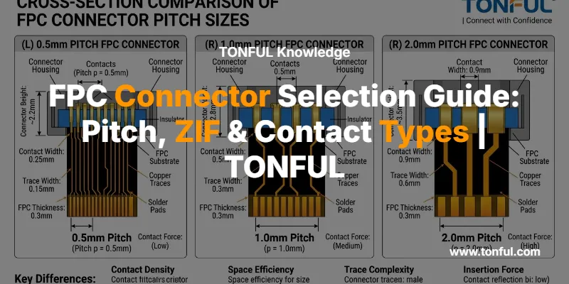
Pitch defines the center-to-center distance between adjacent contacts. This single parameter determines connector size, pin density, current capacity, and assembly complexity.
Common Pitch Standards
| Pitch Size | Typical Applications | Pin Density | Assembly Difficulty | Current per Contact |
|---|---|---|---|---|
| 0.3mm | Wearables, ultra-compact devices | Very High | Very Difficult | 0.3A max |
| 0.5mm | Smartphones, tablets, cameras | High | Moderate | 0.5A typical |
| 1.0mm | Industrial controls, automotive displays | Medium | Easy | 1.0A typical |
| 1.25mm | Appliances, cost-sensitive designs | Medium-Low | Very Easy | 1.5A typical |
| 2.0mm | Power distribution, legacy systems | Low | Very Easy | 2.0A+ |
The 0.5mm pitch dominates modern consumer electronics because it balances space efficiency with practical manufacturability. This pitch allows 20-40 contacts in a 10-20mm connector footprint while remaining compatible with standard SMT assembly equipment. Engineers working on display modules, touch panels, and camera interfaces typically default to 0.5mm pitch unless space or current requirements dictate otherwise.

Smaller pitches enable higher density but introduce challenges. 0.3mm pitch connectors require precise PCB fabrication tolerances, specialized inspection equipment, and careful handling during assembly. Cable alignment becomes critical—misalignment by even 0.1mm can cause contact failure. For high-volume production, 0.5mm and 1.0mm pitches offer better yield rates and lower assembly costs.
Larger pitches (1.25mm, 2.0mm) suit applications requiring higher current capacity or ruggedized connections. Industrial equipment, automotive PCB connectors, and power distribution boards benefit from the mechanical robustness and thermal performance of larger contact spacing.
Contact Position: Top, Bottom, and Dual-Contact Configurations
Contact position determines which side of the FPC cable mates with the connector terminals. This seemingly simple choice affects PCB layout, cable routing, assembly sequence, and product serviceability.
Contact Configuration Comparison
| Configuration | Cable Conductor Side | PCB Routing | Typical Height | Best For |
|---|---|---|---|---|
| Top Contact | Faces away from PCB | Simple, direct | 1.5-3.0mm | Standard assemblies |
| Bottom Contact | Faces toward PCB | Requires via routing | 1.0-2.5mm | Low-profile designs |
| Dual Contact | Both sides engaged | Most flexible | 0.9-2.0mm | High-reliability applications |
Top contact connectors position terminals on the upper surface, engaging the conductor side of the cable when it faces upward. This configuration simplifies PCB trace routing since signals flow directly from connector pads to board traces without vias. Top contact designs dominate in display modules and camera applications where the cable naturally routes away from the board surface.
Bottom contact connectors engage conductors on the cable’s lower surface, requiring the conductor side to face the PCB. This orientation often necessitates via routing to bring signals to the component side, adding minor impedance and cost. However, bottom contact connectors enable lower overall stack height—critical in ultra-thin devices like smartphones and tablets.
Dual-contact connectors engage both cable surfaces simultaneously, providing redundant electrical paths and superior mechanical retention. The dual-spring design resists tension and vibration better than single-sided contacts. Automotive terminals and connectors frequently use dual-contact FPC connectors in applications subject to shock, vibration, and thermal cycling. The trade-off is slightly increased connector height and cost.
Engineers must verify cable construction before specifying contact position. Single-sided FPC cables have conductors on one surface only; dual-sided cables have traces on both surfaces but may still require single-contact connectors if one side carries ground planes or shielding rather than signals.
ZIF vs Non-ZIF Locking Mechanisms
The locking mechanism determines insertion force, retention strength, assembly complexity, and connector durability. ZIF vs non-ZIF FPC connectors represent fundamentally different approaches to cable retention.

ZIF (Zero Insertion Force) Connectors
ZIF connectors use a mechanical actuator—typically a flip-lock or sliding bar—to clamp the cable after insertion. The user inserts the cable with minimal force, then closes the actuator to engage spring contacts against the conductors. This two-step process prevents contact damage during insertion and enables higher contact density in fine-pitch applications.
Advantages:
- Minimal insertion force protects delicate 0.3mm and 0.5mm pitch cables
- Suitable for frequent connect/disconnect cycles (10,000+ mating cycles)
- Reduces assembly line defects from misalignment or excessive force
- Provides tactile feedback when actuator locks
Disadvantages:
- Actuator adds 0.5-1.5mm to connector height
- Higher component cost than non-ZIF equivalents
- Actuator can break if handled roughly during service
- Requires clearance above connector for actuator operation
ZIF connectors dominate in consumer electronics, medical devices, and any application requiring field serviceability. The ability to disconnect and reconnect cables without special tools makes ZIF designs essential for modular products and repair scenarios.
Non-ZIF Connectors
Non-ZIF connectors rely on spring contact friction to retain the cable. The user pushes the cable directly into the connector, compressing spring contacts that grip the conductors. A mechanical lock—often a snap-fit latch—engages automatically when the cable reaches full insertion depth.
Advantages:
- Lower profile (0.6-1.2mm typical height)
- Lower cost per connector
- No moving actuator to break
- Faster single-step assembly
Disadvantages:
- Higher insertion force can damage fine-pitch cables
- Limited to ~50-100 mating cycles
- No tactile confirmation of proper insertion
- Difficult to remove cable without damage
Non-ZIF connectors suit cost-sensitive, high-volume production where cables are installed once during manufacturing and never disconnected. Appliances, toys, and disposable electronics commonly use non-ZIF designs. However, engineers should avoid non-ZIF connectors for pitches below 0.5mm due to cable damage risk.
Cable Thickness and Fit Tolerance
FPC connectors specify compatible cable thickness ranges, typically 0.2mm, 0.3mm, or 0.5mm. Using cables outside this range causes assembly failures or intermittent connections.
Cable Thickness Standards
| Cable Thickness | Typical Construction | Compatible Connectors | Common Issues |
|---|---|---|---|
| 0.2mm | Single-layer FPC, thin FFC | 0.3mm, 0.5mm pitch ZIF | Insufficient contact pressure if connector expects 0.3mm |
| 0.3mm | Standard FPC, most FFC | 0.5mm, 1.0mm pitch ZIF/non-ZIF | Most versatile, widest connector compatibility |
| 0.5mm | Multilayer FPC, reinforced FFC | 1.0mm, 1.25mm pitch | May not fit 0.5mm pitch connectors designed for 0.3mm cables |
| 0.8mm+ | Rigid-flex, stiffened sections | Custom or 2.0mm pitch | Requires connectors with enlarged cable entry |
Cable thickness affects contact normal force—the spring pressure holding conductors against terminals. Insufficient force causes high contact resistance and intermittent signals. Excessive force can crush the cable or prevent the actuator from locking.

Engineers must verify cable construction before connector selection. FPC cables with stiffeners (reinforcing layers at the connector end) may exceed standard thickness specifications. Multilayer FPC designs stack multiple conductor layers with interleaving insulation, increasing total thickness. Always measure actual cable thickness with calipers rather than assuming nominal values.
Connector datasheets specify insertion depth and cable retention force. Proper insertion seats the cable against a mechanical stop inside the connector, ensuring all contacts engage simultaneously. Partial insertion causes contact resistance variation across pins—a common failure mode in high-speed PCB connectors carrying differential signals or precision analog data.
Mounting Technology: SMT, THT, and Press-Fit
FPC connectors attach to PCBs using surface-mount (SMT), through-hole (THT), or press-fit terminations. The choice affects assembly process, mechanical strength, and rework capability.
SMT (Surface Mount Technology) dominates modern production. Connectors solder to PCB pads using reflow ovens, enabling automated assembly and compact board layouts. SMT FPC connectors suit SMT vs THT PCB connectors mass production environments where speed and density matter most. However, SMT joints provide limited mechanical strength—cables under tension can pull connectors off the board. Engineers should add mechanical anchors or strain relief for cables subject to flexing or pulling forces.
THT (Through-Hole Technology) inserts connector pins through PCB holes, creating robust mechanical bonds after wave soldering or selective soldering. THT connectors withstand higher pull forces and survive more thermal cycles than SMT equivalents. Automotive terminals connectors and industrial controls often specify THT mounting for vibration resistance. The trade-off is larger PCB footprint and incompatibility with fully automated SMT assembly lines.
Press-fit technology pushes connector pins into plated PCB holes, forming gas-tight connections without solder. Press-fit vs soldered connectors offer superior reliability in high-vibration environments and eliminate thermal stress from soldering. Press-fit FPC connectors appear in automotive, aerospace, and military applications where connection integrity outweighs cost considerations.
Application-Specific Selection Criteria
Consumer Electronics
Smartphones, tablets, and wearables prioritize miniaturization and cost. Specify 0.5mm pitch, bottom-contact or dual-contact, ZIF locking, and SMT mounting. Cable thickness typically 0.3mm. Verify connector height fits within device stack-up and that actuator operation doesn’t interfere with adjacent components.
Automotive Systems
Automotive PCB connectors must survive -40°C to +125°C temperature cycling, vibration per ISO 16750, and salt spray exposure. Specify 1.0mm pitch minimum, dual-contact configuration, THT or press-fit mounting, and gold-plated contacts for corrosion resistance. ZIF connectors with reinforced actuators handle service disconnection for diagnostics and repair.
Industrial Controls
Industrial applications balance cost, reliability, and serviceability. 1.0mm or 1.25mm pitch provides adequate density while simplifying assembly. ZIF connectors enable field maintenance. Specify connectors with locking features rated for the expected vibration environment. Consider conformal coating compatibility if the assembly will be sealed against moisture or contaminants.
Medical Devices
Medical electronics require traceability, biocompatibility documentation, and high reliability. Specify connectors from manufacturers with ISO 13485 certification. ZIF designs enable sterilization and service. Gold plating prevents corrosion in body-fluid exposure scenarios. Verify connector materials comply with USP Class VI or ISO 10993 biocompatibility standards.
Selection Checklist
Before specifying an FPC connector, verify:
- [ ] Pitch matches cable conductor spacing (0.3mm, 0.5mm, 1.0mm, 1.25mm, 2.0mm)
- [ ] Pin count matches cable circuit count with appropriate orientation
- [ ] Contact position (top/bottom/dual) matches cable conductor side and PCB routing
- [ ] Cable thickness falls within connector specification (0.2mm, 0.3mm, 0.5mm)
- [ ] Locking mechanism (ZIF/non-ZIF) suits assembly process and service requirements
- [ ] Mounting type (SMT/THT/press-fit) compatible with PCB and assembly process
- [ ] Connector height fits within product stack-up with actuator clearance
- [ ] Current rating per contact meets power delivery requirements
- [ ] Operating temperature range covers application environment
- [ ] Mating cycle rating exceeds expected connect/disconnect operations
- [ ] Contact plating (tin/gold) appropriate for environment and signal type
- [ ] Orientation (right-angle/vertical) matches cable routing path

Common Selection Mistakes
Mismatched pitch: Using a 0.5mm pitch connector with a 1.0mm pitch cable creates open circuits. Always verify cable and connector pitch match exactly.
Wrong contact orientation: Installing a top-contact connector when the cable has bottom-side conductors prevents electrical connection. Check cable construction drawings before ordering connectors.
Insufficient cable thickness tolerance: Connectors designed for 0.3mm cables may not lock properly with 0.5mm cables, even if pitch and pin count match.
Ignoring actuator clearance: ZIF connectors require 2-5mm clearance above the connector for actuator operation. Components placed too close prevent the actuator from opening.
Inadequate mechanical support: SMT connectors on flexible PCBs or cables under tension require additional mechanical anchoring. Consider THT mounting or adhesive anchors for high-stress applications.
Integration with Wire Harness Assemblies
FPC connectors often terminate custom wire harness assemblies in complex products. When integrating FPC connections into larger harness systems, coordinate connector selection with harness routing, strain relief, and service access requirements. TONFUL Electric provides terminals and connectors including FPC/FFC solutions as part of complete interconnect systems.
For applications requiring multiple connector types—such as combining FPC connectors with wafer connectors or female header connectors—consult TONFUL’s wafer connector cross-reference guide and female header connector pitch guide to ensure compatible footprints and assembly processes.
FAQ
Q: Can I use an FFC cable with an FPC connector?
A: Yes, if pitch, pin count, conductor position, and thickness match. FFC cables have simpler construction than FPC but use the same connector footprints. Verify the cable thickness specification—some FFC cables are thicker than equivalent FPC cables.
Q: What’s the difference between 0.5mm and 1.0mm pitch in practical terms?
A: 0.5mm pitch provides twice the pin density in the same linear space, enabling smaller connectors. However, 1.0mm pitch offers easier assembly, higher current capacity per contact, and better tolerance to manufacturing variations. Choose based on space constraints and current requirements.
Q: How many mating cycles can I expect from a ZIF connector?
A: Quality ZIF connectors typically rate for 10,000-50,000 mating cycles. Non-ZIF connectors rate for 50-500 cycles. Actual life depends on insertion technique, cable quality, and environmental factors. For service-intensive applications, specify connectors with documented cycle testing.
Q: Do I need gold plating or is tin plating sufficient?
A: Tin plating suits most consumer electronics and benign environments. Gold plating prevents corrosion in harsh environments (automotive, marine, industrial), low-voltage signals, and applications requiring long-term reliability. Gold adds cost but eliminates contact resistance growth over time.
Q: Can I replace a damaged ZIF actuator without replacing the entire connector?
A: Some connector families offer replacement actuators, but most require full connector replacement. ZIF connectors with modular actuators cost more initially but reduce repair costs. Check manufacturer documentation for serviceability options.
Conclusion
Selecting the right FPC connector requires matching pitch, contact configuration, locking mechanism, and cable specifications to your application requirements. Start with pitch and pin count, verify contact orientation matches your cable, choose ZIF or non-ZIF based on assembly process and service needs, and confirm cable thickness compatibility. Consider mounting technology, environmental requirements, and mechanical stress when finalizing the specification.
TONFUL Electric manufactures FPC/FFC connectors and complete electrical PCB connector solutions for automotive, industrial, consumer, and medical applications. Our engineering team provides connector selection support, custom cable assemblies, and integration with broader interconnect systems. Contact TONFUL for connector samples, technical specifications, and application engineering assistance.
