
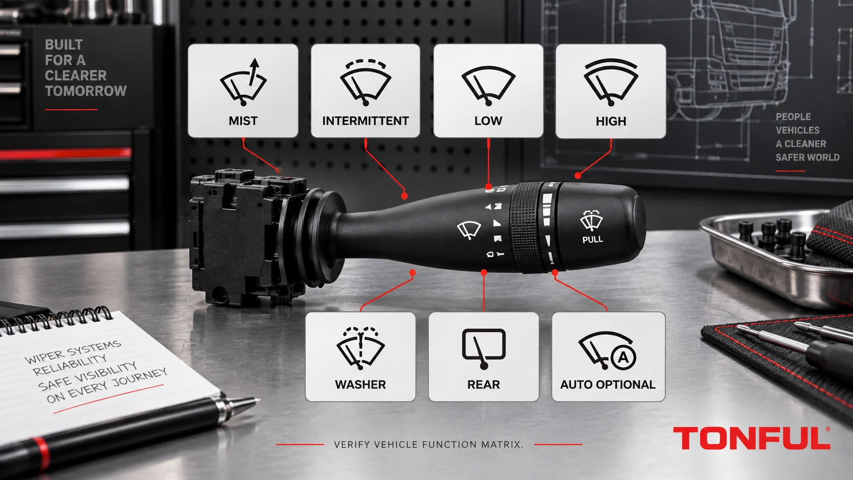
Two wiper stalks can share the same connector and basic symbols while producing different behavior. One may have a momentary mist position, fixed intermittent delay, variable delay ring, two continuous speeds and washer pull; another may add rear-wiper stages, rain-sensor sensitivity or a module-coded command. If buyers compare only OFF/LOW/HIGH, the overlooked functions often become the reason a replacement is returned.
The correct selection method is to document every physical position and trace what the switch sends to the vehicle. The stalk may carry motor or relay current, present a resistance-coded input, or send a module/network request. This guide does not publish a universal pinout, delay time or resistor value; those must come from the exact vehicle diagram, product drawing and approved sample.
On this page: Build the Function Matrix | Identify the Electrical Architecture | Test and Diagnose | Release Checklist
Build the Function Matrix
Define Each Front-Wiper State
| Function | Typical driver action | What must be verified | Common selection error |
|---|---|---|---|
| OFF/Park request | Stalk at rest | Park circuit or controller state and final blade position | Assuming OFF simply removes all power |
| Mist | Momentary lever movement | Return action, single-cycle request and controller recognition | Confusing mist with the first maintained speed |
| Intermittent | Maintained interval position | Fixed or variable delay architecture and approved stages | Matching the symbol but not the delay input |
| Variable interval | Rotary ring or multi-step control | Direction, number of states and coded values | Reversed ring or wrong resistance windows |
| LOW | Maintained continuous wipe | Correct command and motor/relay/module output | Treating motor speed fault as stalk fault |
| HIGH | Maintained continuous wipe | Separate command path and transition behavior | Candidate omits or swaps the high state |
| Front washer | Pull, push or end button | Momentary return, pump request and wipe-after-wash logic | Assuming the stalk directly powers the pump |
Typical describes common interfaces, not a universal sequence. On one vehicle, mist may produce one wipe through the BCM; on another, the motor park circuit and relay logic determine completion. Record the actual lever direction, maintained/momentary behavior, symbols and response from the removed part and vehicle handbook.
Record Rear Wiper and Advanced Functions Separately
Rear-wiper OFF, intermittent, continuous and wash may use a rotary end cap, a push/pull action or another control. A front-only replacement can fit physically but leave the rear circuit unavailable. Likewise, rain-sensor sensitivity can share a ring that resembles a variable-delay control while the receiving module interprets it differently.
Do not treat “AUTO” or a raindrop symbol as proof of a rain sensor. Confirm the vehicle option, sensor/module architecture, stalk state and initialization requirements. The DENSO article on advanced wiper systems illustrates that modern wiping/washer arrangements can require like-for-like system components; it concerns named blade/fluid-delivery technology and does not establish stalk compatibility.
Capture the Removed Part and Vehicle
Record vehicle, market, model, production or VIN/chassis boundary, cab/body, LHD/RHD, stalk side, front/rear wiper options and rain-sensor equipment. Photograph every symbol and control in OFF, each detent and each momentary position. Capture the complete OE number, suffix, revision, housing and connector.
The wiper-switch failure guide helps separate selection evidence from symptom-based diagnosis. Do not infer a replacement number from a fault description alone.

Map every actual detent, rotary stage and momentary action; functions shown are a verification framework, not a universal sequence.
Identify the Electrical Architecture
Direct Motor or Relay-Controlled Paths
Older or simpler circuits may route motor, park or relay-coil paths through stalk contacts. The park circuit can remain energized after the driver selects OFF so the blades return to their designed rest position. Testing OFF as “all terminals open” can therefore be wrong.
Trace battery protection, switch, relays, motor windings, park contact and ground from the vehicle diagram. For loaded switch paths, verify the specified current profile, switching sequence, voltage drop and thermal behavior. For relay control, separate the coil/request side from relay contacts and motor output. The LED versus incandescent load-path guide uses lighting examples but its direct/relay/module distinction also helps organize wiper control evidence.
Resistance/Voltage-Coded Inputs
A resistor ladder can encode OFF, intermittent stages, LOW/HIGH or sensitivity values on shared conductors. Compatibility depends on reference supply, return, nominal windows, tolerance, contact contribution, temperature and receiving-module thresholds. A loose-switch ohmmeter value may differ from the installed voltage because the module input is part of the circuit.
Record raw values and the module-decoded state. Do not publish one vehicle’s values as universal. If adjacent positions overlap or drift intermittently, investigate contacts, resistor network, connector and reference/ground before replacing the motor.
BCM, LIN and CAN Requests
An electronic stalk or steering-column module may send wiper requests to a BCM or another controller, which then manages relays, smart power outputs, motor park logic, wipe-after-wash and diagnostics. Confirm supply, ground, wake state, local input recognition, network communication, software/configuration and DTC behavior.
The analog, resistive, LIN and CAN stalk guide explains these interface types. A valid network message does not prove the downstream motor, pump or mechanical linkage is healthy.
Regulatory Boundary
For applicable U.S. vehicles, 49 CFR §571.104 addresses vehicle-level windshield wiping and washing system requirements. It is not a universal stalk-switch specification and does not provide a generic pinout, interval timing or component approval. Completed-vehicle compliance cannot be inferred from a replacement switch bench test alone.
Test and Diagnose
Use a Copyable State Record
| Record field | Removed part | Candidate sample | Acceptance source | Result |
|---|---|---|---|---|
| OE number, suffix and revision | Enter | Enter | Label/catalog | Pass/Fail |
| Connector orientation/cavities | Enter | Enter | Drawing/end-view photo | Pass/Fail |
| OFF/park behavior | Enter | Enter | Vehicle diagram/test | Pass/Fail |
| Mist action and return | Enter | Enter | Function matrix | Pass/Fail |
| Intermittent stages | Enter | Enter | Function matrix | Pass/Fail |
| Variable ring direction/states | Enter | Enter | Product-specific plan | Pass/Fail |
| LOW and HIGH states | Enter | Enter | Diagram/test | Pass/Fail |
| Front washer/wipe-after-wash | Enter | Enter | Vehicle procedure | Pass/Fail |
| Rear wiper/washer states | Enter | Enter | Option-specific matrix | Pass/Fail |
| AUTO/sensitivity, if fitted | Enter | Enter | Vehicle option and diagnostics | Pass/Fail |
| Architecture/coding/DTCs | Enter | Enter | Wiring/service information | Pass/Fail |
| Installed disposition | Reference | Sample/lot | Approval record | Approved/Conditional/Rejected |
For discrete contacts, test all states and transitions using controlled cavity numbers. For coded inputs, retain raw and decoded results with instrument, supply and temperature conditions. For module/network inputs, record live stalk states and downstream commands separately. Never bridge unidentified terminals or apply battery voltage to a signal line.
Use the combination-switch pinout and connector guide to fix the connector viewing direction and cavity numbering before recording any state. A correct electrical result assigned to a mirrored connector view is still an unusable and potentially hazardous record.
Follow a Diagnostic Order
Start by documenting the symptom and initial DTCs. Inspect fuse/protection, connector seating, terminals, grounds, motor linkage and washer-fluid/mechanical conditions. Observe the stalk input, then controller/relay output, motor or pump supply and final mechanism. This sequence prevents a worn blade, seized linkage, empty reservoir, blocked nozzle, motor park fault or wiring problem from being mislabeled as a switch defect.
| Symptom | More likely directions | Next evidence |
|---|---|---|
| Mist works only while held but does not complete cycle | Park circuit, controller logic or wrong variant | Input request and park/output trace |
| Intermittent acts as continuous | Wrong coded value, relay/controller fault or wrong stalk | Raw state and module-decoded command |
| Variable ring operates backward | Wrong variant, orientation or coded mapping | Ring direction and state table |
| LOW works but HIGH does not | Separate switch path, relay, motor winding or module output | Input and downstream output separately |
| Washer pump runs but wipers do not | Wipe-after-wash logic, relay/output or motor path | Pump request and wipe command/output |
| Wipers run but pump does not | Washer contact/input, pump circuit, fluid or nozzle | Switch request and pump supply |
| Rear functions are absent | Front-only switch or wrong option configuration | Rear-control presence and module state |
| AUTO mode is erratic | Sensor, calibration, glass condition, stalk input or configuration | Sensor/module diagnostics and option data |

Separate the stalk request from controller, relay, motor, park mechanism, pump and washer-fluid evidence.
Release Checklist
Approve only when vehicle scope, complete OE chain, symbols, every detent and momentary action, connector/cavity map, architecture, raw and decoded states, park behavior, front/rear washer functions, optional AUTO logic, coding and installed operation meet controlled requirements. Record sample/lot, instruments, document revisions, DTCs, approver and date.
Control changes to stalk legends, rotary mechanism, contacts, resistor network, connector, PCB, software, housing, tooling and end-of-line test. Incoming inspection should verify the approved label, symbols, detents/returns, connector orientation and basic electrical identity before stock is mixed.
Work With TONFUL
TONFUL’s automotive combination switch range presents current application references. Send the exact vehicle/VIN scope, complete OE label, front and rear wiper options, rain-sensor status, stalk/connector photos, required function matrix and validation plan. TONFUL can compare the candidate with controlled product evidence and an approved sample; matching OFF/LOW/HIGH symbols alone is not treated as full compatibility.