
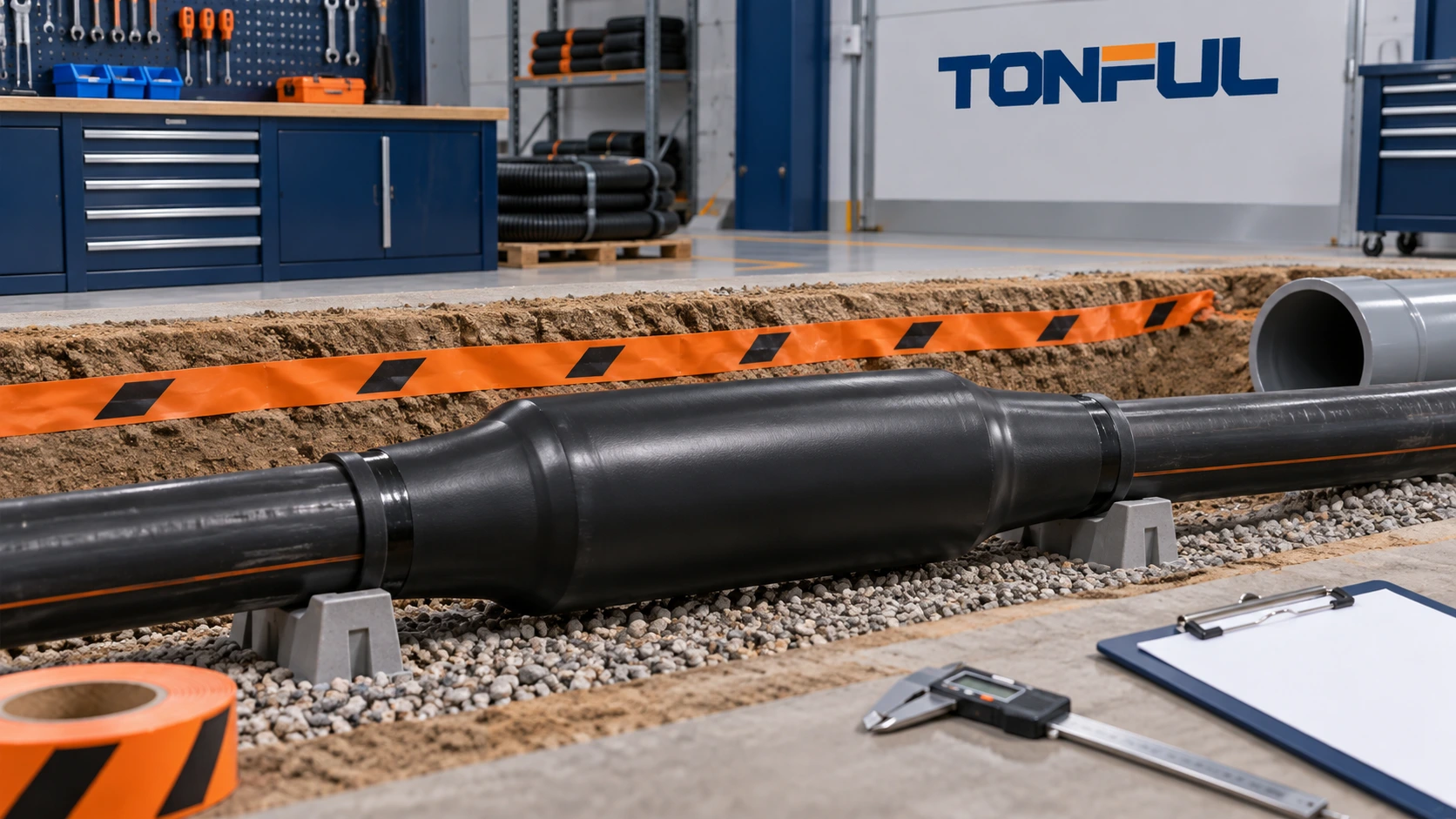
Heavy-wall heat shrink tubing can provide rugged insulation, jacketing and environmental protection for some underground cable repairs, joints and terminations. It is not a universal substitute for a cable splice kit, molded joint, enclosure or utility-approved accessory. The correct solution depends on the cable system, voltage, conductor connection, shield and neutral design, water exposure, soil, mechanical protection and approved installation procedure.
Safety comes first. Before any excavation in the United States, contact 811 or the applicable state one-call service, submit the locate request and wait for the required utility markings. Rules and waiting periods vary by location. Privately installed circuits may require site records or private locating because they may not be covered by the public utility process. Never assume that a damaged cable is the only buried service in the area.
Define the Repair Scope Before Selecting Tubing
Identify what failed and what the heat shrink is expected to do. A superficial outer-jacket repair is different from a conductor splice, shield repair, neutral reconstruction or complete joint. Record cable type, manufacturer, voltage class, conductor material and size, insulation system, shield, concentric neutral or armor, jacket, accessories and installation environment.
| Repair scope | Possible heat-shrink role | Additional system evidence required |
|---|---|---|
| Outer-jacket damage only | Rejacketing and mechanical/environmental protection | Cable maker repair procedure and jacket compatibility |
| Low-voltage conductor splice | Insulation, sealing and strain relief within an approved design | Connector, electrical insulation and completed-splice qualification |
| Shielded cable joint | Outer protection may be one layer of the system | Stress control, shield continuity, grounding and accessory instructions |
| Armored cable | External sealing or rejacketing where approved | Armor continuity, bonding and corrosion control |
| Transition or termination | Cable-to-accessory sealing and protection | Exact termination kit and manufacturer procedure |
Do not cover damaged insulation, corroded strands or an unapproved connector and call the repair complete. Isolate and de-energize the circuit using the owner’s electrical safety procedure. Underground and power-cable work should be performed by qualified personnel with the correct cable documentation, test equipment and authority approval.
Underground Utility Safety and Site Control
The official 811 safe-digging program explains that excavators must provide accurate site information and sufficient notice for utility locating. The locate process does not identify the electrical condition of the exposed cable or approve the repair. Maintain required tolerance-zone, excavation and damage-reporting practices under local rules.
After utilities are marked, plan access that avoids new cable damage. Control water, trench stability, traffic, weather and contamination. Do not use a heat source near standing water, flammable atmospheres or uncontrolled combustible material. The installer needs safe clearance around the full cable circumference; an inaccessible underside can prevent complete recovery and sealing.
Photograph the site before disturbing the cable. Record burial arrangement, conduit or direct-buried condition, bedding, warning tape, mechanical guards and evidence of impact, rodents, water, chemicals or thermal damage. These observations help distinguish the initiating failure from damage created during excavation.

Utility locating, electrical isolation and repair-scope approval must occur before tubing selection or heat application.
Choose a Product Approved for the Exact Application
“Heavy wall,” “adhesive lined” and “direct burial” are separate attributes. Heavy wall describes a robust wall category. Adhesive lining identifies a sealing construction. Direct-burial suitability is a product-specific claim tied to defined installation conditions and evidence. One attribute does not prove the others.
The thin-, medium- and heavy-wall comparison explains why wall-class labels do not create universal thickness or application boundaries across suppliers.
The official 3M ITCSN heavy-wall sleeve page provides an example of a named product family with specific direct-buried and submersible applications, listed sizes, constructions and certification scope. Those statements apply only to the identified 3M products and conditions; they cannot be transferred to unverified tubing with a similar appearance.
TE Connectivity’s official WCSM thick-wall product page similarly describes a specific tubing family for cable sealing, protection and jacketing. Use manufacturer pages to understand the type of evidence required, not to create generic performance claims for all heavy-wall tubing.
For a proposed TONFUL product, request the controlled drawing, product data, liner description, cable compatibility, installation instruction and applicable test or approval documents. Confirm size, color and construction because a family may include coated and uncoated variants.
Size the Sleeve From Geometry, Not Cable Name
Measure the largest feature the unshrunk tube must pass over: connector, lug, splice barrel, shield reconstruction, armor transition or cable jacket. Then measure the smallest surface the tubing must recover onto. The expanded inside diameter must clear the largest feature, and the maximum recovered inside diameter must produce the required fit on the smallest surface.
The heat shrink tubing size guide explains this pass-over and recovery check. For an underground joint, also record transition slopes, eccentricity, branch geometry, overlap and available straight cable length. A sleeve that fits the center can still bridge at an abrupt shoulder or fail to seal on the cable jacket.
Recovered wall and length change matter. Too much recovery can increase stiffness, alter wall distribution and move sleeve ends away from intended seal zones. Too little recovery may leave weak contact pressure or incomplete adhesive flow. Use production-intent components for fit trials rather than relying on a nominal cable size.

Size the sleeve against the complete splice geometry, including the largest pass-over feature and both jacket seal surfaces.
Seal Design and Surface Preparation
An adhesive-lined sleeve seals only when the liner is compatible with the substrates, the surfaces are prepared correctly and the process produces continuous coverage. Cable jackets can differ in polymer, texture, contamination and aging. Soil, water, pulling lubricant, oxidation and handling residues can interfere with adhesion.
Follow the approved product and cable procedure for cleaning, abrasion or priming. Do not substitute solvents or roughen a jacket without permission. Mark the sleeve location and minimum overlap on sound jacket. If the cable is wet internally or water is migrating along conductors, an outer sleeve alone may trap moisture instead of correcting the cause.
During installation, observe adhesive behavior at both ends without treating visible beads as the only acceptance criterion. The center and underside must also recover correctly. Define acceptable end flow, voids, wrinkles, splits, scorching and sleeve position in the work instruction. For irregular transitions, sectioned qualification samples can confirm internal coverage.
Heavy wall can add mechanical protection, but it does not replace guards, conduit, bedding or depth requirements. Restore the system according to local rules, cable type, owner standards, vehicle loading, future excavation risk and manufacturer instructions. Do not publish one universal burial depth.
Electrical-System Boundaries
For a conductor splice, approve the connector and insulation system together. Record conductor metal, construction, size, preparation, connector, tool, die, crimp or shear-bolt settings, number of compressions and inspection criteria. Heat shrink cannot correct a loose, undercrimped, contaminated or overheated electrical joint.
For shielded medium-voltage cable, electrical stress control, semiconductive layers, shield continuity and grounding are critical. A heavy-wall outer sleeve may protect the completed joint but does not create these functions by itself. Use the exact cable accessory kit and qualified procedure. Similarly, armor and concentric neutral conductors require approved continuity and corrosion-control methods.
Voltage claims must remain product- and system-specific. Material dielectric strength or wall thickness cannot be converted directly into a universal cable voltage rating. Test specimen geometry, conditioning and field distribution differ from an installed joint. Preserve the cable manufacturer or system designer’s acceptance source in the repair record.
Control the Heating Process in the Trench
Heavy-wall tubing has substantial thermal mass. The outer surface can appear recovered while adhesive or the inner wall remains incomplete around the joint. Establish the heating method and window using qualification trials. A small heat gun may be slow or uneven on large cable; open-flame tools introduce additional hazards and may only be used when the product procedure, site controls and qualified personnel permit them.
Record heat source, equipment ID, fuel or power condition, nozzle, distance, motion, heating sequence, cable temperature limits and cooling. Heat from the center toward the ends when required by the approved instructions so air and excess sealant can move outward. Support the cable to maintain alignment and keep the sleeve accessible around its circumference.
Use the heat gun, oven and infrared process guide for general process comparison, but follow the selected product’s field-installation instruction. Protect nearby cable insulation, labels and accessories from overheating. Do not backfill until the repair has cooled, inspection is complete and the procedure permits it.

A qualified field process must control heat around the full circumference and preserve the cable system beneath the sleeve.
Validate Moisture and Mechanical Protection
A credible validation plan begins with sample identity and an unaged baseline. Use the actual cable jackets, splice geometry, connector and production process. Decide which tests use independent samples and which use a specified sequence. Water exposure followed by thermal cycling and mechanical loading can reveal interactions that separate tests miss.
| Validation area | Controlled conditions | Evidence to retain |
|---|---|---|
| Dimensions | Expanded ID, recovered ID, wall, length and overlap | Raw measurements and drawing limits |
| Installation | Heat source, sequence, time, cable and ambient condition | Process record and complete photographs |
| Seal | Water method, pressure or depth, duration and temperature | Leak/ingress result and section evidence |
| Thermal | Cycling or aging profile and sample state | Initial, interim and final observations |
| Mechanical | Impact, abrasion, bending, pulling or backfill simulation | Load/cycles, failure mode and disposition |
| Electrical | Test points, voltage/current method and conditioning | Result and system acceptance source |
| Corrosion | Metal interfaces, solution and exposure sequence | Visual, electrical and material findings |
The heat shrink tubing testing guide provides sample-allocation and evidence principles. A demonstration in a bucket is not automatically a direct-burial qualification. Match the method, specimens and acceptance criteria to the project requirement.
Inspection, Backfill and Traceability
Before backfill, verify sleeve identity, location, overlap, circumferential recovery, end condition, absence of splits or scorching and completion of any required electrical tests. Photograph the entire circumference and both ends. Record cable ID, route, coordinates or station, repair date, personnel, product lot, connector lot, equipment and inspection result.
Restore bedding, guards, warning tape, conduit seals and other protective elements according to the owner’s design. Backfill material and compaction should not damage or displace the repair. Where a manufacturer permits immediate backfill for a named product, follow that exact instruction; do not generalize the statement to other sleeves.
Monitor repeat failures by location, cable type, cause and repair method. A recurring water or impact problem may require drainage, routing, mechanical protection or system redesign rather than another sleeve. Retain change notifications and incoming-inspection controls for future repair stock.
For repeat purchasing, use the heat shrink tubing RFQ checklist to preserve cable geometry, liner, test evidence, packaging and change-control requirements in the quotation.

A complete repair record connects the buried asset, materials, process, test evidence and backfill release decision.
Work With TONFUL
Send TONFUL the cable-system description, repair scope, voltage class, largest and smallest diameters, sleeve length, jacket material, liner requirement, water and soil exposure, mechanical risks, installation method, required standards and annual volume. TONFUL can discuss heavy-wall heat shrink candidates and production-intent samples. Final approval must remain tied to the exact product, cable system and validated field procedure.
—