
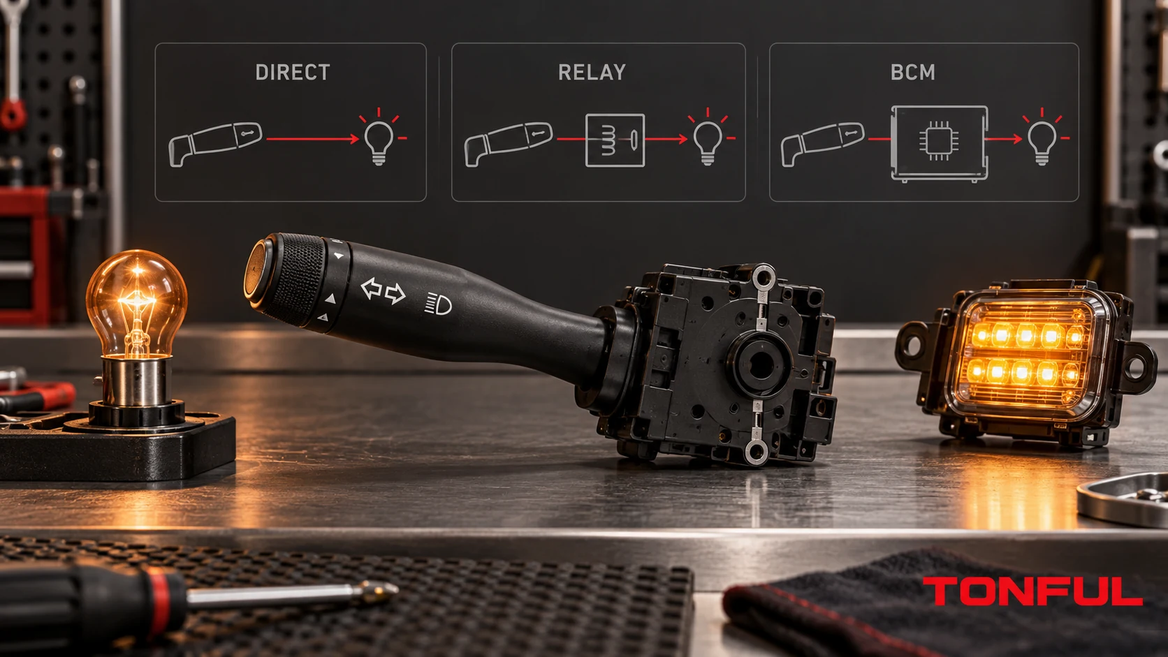
Changing an incandescent lamp to LED can produce rapid flashing, warnings, faint glow, flicker or no output even when the combination switch is healthy. The reason is that the stalk may carry full lamp current, switch only a relay coil, provide a low-current input to a body control module (BCM), or send a coded or network request. Until that architecture is known, comparing lamp wattage or testing continuity at the stalk can lead to the wrong conclusion.
This guide explains how to identify the current path, what changes when LED replaces incandescent, and which evidence is needed before approving a switch or lighting conversion. It does not provide a universal current rating, resistor value, pinout or retrofit method; those must come from the controlled vehicle diagram, switch specification, lamp documentation and approved test plan.
On this page: Find the Load Path | Compare LED and Incandescent Behavior | Test the Correct Interface | Release Checklist
Find the Load Path
Four Common Control Architectures
| Architecture | Combination-switch role | Where lamp current is switched | Evidence required |
|---|---|---|---|
| Direct load | Contacts complete the lamp supply or return path | Inside stalk contacts and downstream wiring | Vehicle diagram, contact path, load profile, voltage drop and temperature evidence |
| Relay controlled | Stalk energizes or grounds a relay coil | Relay contacts | Coil circuit, suppression, relay rating and lamp-side protection |
| BCM or smart high-side control | Stalk sends a discrete, coded or low-current request | Semiconductor output in BCM or power module | Input logic, output-channel configuration, diagnosis and protection behavior |
| Networked switch | Stalk electronics send a LIN/CAN or other defined message | Remote controller or lighting ECU | Network interface, software/configuration, message recognition and DTC evidence |
A single combination switch may mix these methods. For example, one contact may command a relay while another function is resistance coded and a third is interpreted by a local module. The combination switch pinout guide is useful for documenting connector orientation and state tables, but the vehicle-specific diagram remains the authority for the actual current path.
How to Tell Whether the Stalk Carries Lamp Current
Trace the circuit from battery protection to the lamp, not merely from the switch connector. If the diagram shows supply or ground passing through stalk contacts and continuing to the lamps, the contacts may be in the load path. If the stalk terminates at a relay coil or controller input, it usually carries only that interface current. If the connector contains module power, ground and communication conductors, lamp power may be switched elsewhere entirely.
Terminal size can support an investigation but cannot prove the architecture. Large terminals may serve another direct-load function, and small terminals may share coded signals. A continuity beep can identify a closed contact but cannot establish current capacity, voltage drop under load, thermal behavior, inrush capability or compatibility with an electronic controller.

Trace the controlled vehicle diagram to identify where lamp current is actually switched; this diagram is conceptual and not a universal pinout.
Why the Difference Matters to Switch Approval
For a direct-load switch, contact material, geometry, spring force, terminal interface, conductor path and arc behavior all influence performance. Approval should address the specified steady load, switching event, inrush, voltage drop, temperature rise, endurance sequence and fault protection. Lower steady LED power does not automatically make the application easier because an LED driver can present input capacitance, short pulses or diagnostic interactions that differ from a hot incandescent filament.
For a relay or BCM request, the stalk must instead reproduce the correct logic. The relevant checks may be coil current and suppression, pull-up or pull-down behavior, resistance windows, reference voltage, debounce, network state or software configuration. A switch can be mechanically and electrically sound yet incompatible with the receiving input.
Compare LED and Incandescent Behavior
Incandescent and LED Loads Are Electrically Different
An incandescent filament is primarily a resistive thermal load in normal operation, but its cold resistance is lower than its hot resistance, creating an inrush when first energized. The filament’s current consumption has also been used by traditional flasher and lamp-out systems as evidence that the lamp is present.
An automotive LED lamp includes semiconductor emitters and usually driver electronics. Its input may look capacitive, electronically regulated or pulse dependent rather than like a filament. Depending on design, the lamp may draw lower steady current, react to diagnostic pulses, use PWM for dimming, or report faults through a defined interface. These are product- and vehicle-specific behaviors, not universal characteristics of every LED lamp.
TI’s automotive PWM LED-driver reference design illustrates that LED lighting may use regulated driver electronics and PWM while operating through automotive supply conditions. It is a design example, not proof that a particular vehicle, lamp or TONFUL switch uses that circuit.
Lamp-Out Detection and Rapid Flashing
Traditional systems may interpret lower LED current as an open lamp and respond with a warning or changed flash rate. Adding an arbitrary resistor can increase current, heat and wiring stress while masking rather than correctly solving a compatibility problem. Use only the vehicle or lamp manufacturer’s approved method, and verify the location, rating, thermal mounting and diagnostic consequences of any specified component.
HELLA describes purpose-designed LED flasher units and ISO-pulse-compatible lamps that allow defined failure monitoring. Its LED flasher technical information applies to the listed HELLA products and configurations; it does not mean every LED lamp is interchangeable with an incandescent bulb or that every combination switch supports both.
PWM, Diagnostic Pulses and Faint Glow
A BCM may use low-energy checks to detect an open load when the lamp is off or may monitor current while it is on. Some LED drivers respond visibly to energy that was too small to light a filament, producing a faint glow or periodic flash. PWM outputs can also create meter readings that appear unstable if the instrument and method are not appropriate for the waveform.
Infineon’s SPIDER+ LED smart-switch information shows a BCM-style implementation with PWM and open-load diagnosis. It supports the principle that the controller output and diagnostic thresholds matter; its device-specific features and values are not universal vehicle requirements.
Test the Correct Interface
Build a Load-Path Verification Record
| Record field | Required entry |
|---|---|
| Vehicle identity | Make, model, market, production or VIN/chassis boundary and options |
| Switch identity | Full OE/supplier number, suffix, revision, sample and lot |
| Lighting function | Turn, hazard, position, headlamp, fog lamp or other named channel |
| Control architecture | Direct load, relay, BCM input, coded input or network request |
| Switch test points | Controlled cavity numbers, view direction and conductor path |
| Lamp technology | Incandescent or LED, exact approved model and driver/control type |
| Electrical conditions | Supply range, switching state, load profile and temperature from approved plan |
| Measurements | Raw current, voltage drop, waveform, temperature or diagnostic state as applicable |
| Acceptance source | Vehicle specification, product drawing, customer plan or approved deviation |
| Disposition | Pass, conditional or reject, reviewer and date |
For direct-load paths, measure voltage drop across the complete identified switch path while the specified load is operating. Record supply voltage, current, test points, ambient and stabilization condition. Inspect terminals and connector interfaces for heat evidence. Contact resistance measured at low current may help compare samples, but it does not replace loaded verification when the product specification requires it. See TONFUL’s contact-resistance testing guide for method controls.
For relay-controlled circuits, separate the coil side from the contact/load side. Confirm the stalk request at the relay coil, then verify relay output and lamp feed independently. A failed lamp path or relay contact should not be assigned to the stalk merely because the driver operates the stalk first.
For BCM or networked circuits, observe the input state and commanded output with approved diagnostic equipment. Compare command, output, current diagnosis and DTC status. Do not bridge controller pins, substitute loads or add resistors unless the controlled service or engineering procedure permits it.
Use a Symptom-to-Evidence Matrix
| Symptom | Plausible directions | Next check |
|---|---|---|
| LED turn signals flash rapidly | Lamp-out strategy, incompatible flasher or configuration | Approved lamp/flasher combination and controller diagnosis |
| LED glows when switched off | Off-state diagnostic pulse or leakage path | Scope waveform, controller strategy and lamp-driver compatibility |
| Incandescent works but LED does not | Polarity, driver supply range, PWM or diagnostic incompatibility | Lamp documentation and output waveform |
| LED works but warning remains | Current threshold or communication requirement not satisfied | Diagnostic status and approved coding/solution |
| Switch or connector heats | Direct-load resistance, poor terminal contact or excessive current | Loaded voltage drop, current, terminal retention and thermal evidence |
| Relay clicks but lamp stays off | Load-side supply, relay contact, protection, ground or lamp fault | Relay output and downstream voltage-drop checks |
| Scan tool sees command but output is absent | Controller inhibit, DTC, configuration or protected channel | Output authorization, fault record and recovery procedure |
| Only one stalk function fails after conversion | Separate channel, pinout or shared-ground issue | Function-specific diagram and cavity/state matrix |

Measure the interface that belongs to the identified architecture rather than treating every stalk as a direct lamp switch.
Release Checklist
Before approving a replacement switch or lamp conversion, confirm the exact vehicle and market, switch OE chain, connector and populated cavities, lighting-channel architecture, lamp model, voltage domain, load and inrush profile, PWM or diagnostic behavior, failure indication and protection strategy. Test every related stalk function and retain initial, operating and post-test evidence under the approved conditions.
Do not infer compatibility from lower LED wattage. Do not claim that a relay automatically isolates every switch contact, or that the same connector means the same BCM input. A conversion is approved only within its documented vehicle, lamp, switch and controller scope. The combination switch diagnostic guide can help separate switch evidence from relays, wiring, grounds, controllers and lamps.
Work With TONFUL
TONFUL’s automotive combination switch range covers current application references for sourcing projects. Send the vehicle and market, production boundary, complete OE number, connector end view, pinout, lighting architecture, lamp type, load profile and required validation plan. TONFUL can review the switch configuration against controlled product evidence and an approved sample; LED or incandescent compatibility is not assumed from appearance or nominal voltage alone.