
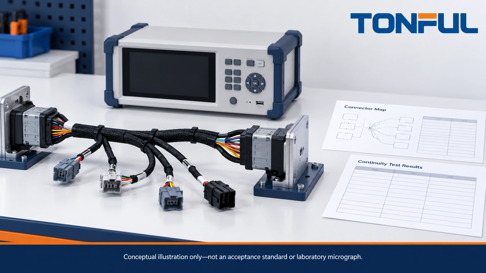
Wire harness continuity testing checks whether the assembly contains the intended electrical connections and avoids prohibited connections within defined test conditions. It can reveal missing wires, crossed circuits and unintended conductive paths. It cannot, by itself, prove adequate terminal retention, loaded voltage drop, insulation endurance or successful operation in the vehicle or machine.
A defensible production test needs more than a green indicator. The pinout, program, fixture, resistance limits and unit record must belong to the same released configuration. This guide explains how buyers and quality teams can establish that chain, investigate failures and release only the scope supported by the results.
Define the Connection Map and Required Fault Coverage
Identify every test point and intended net
Begin with the approved schematic, connector end views and wire list. State whether each view shows the mating face or wire-entry side. Record key orientation, cavity numbering and populated positions. Include shield connections, splice branches and unused cavities where they affect the required coverage.
A net contains points intentionally connected together. The test definition should distinguish those points from points that must remain isolated. Do not omit prohibited connections merely because the expected connections passed. A harness can contain every required path and still include an unintended bridge between two circuits.
Review the map independently against the design source. Learning a program from an assembly is convenient, but a learned sample can preserve its own wiring error. Confirm the learned data before it becomes the acceptance reference. Keep the reviewer, revision and effective configuration with the program approval.
Distinguish opens, shorts and miswires
An open occurs when an intended connection is absent or exceeds the approved connection threshold. A short is an unintended connection detected under the defined isolation conditions. A miswire places a circuit at the wrong endpoint; the resulting report may show an open to the correct destination and an unintended connection elsewhere.
| Reported condition | Product possibilities | Checks before disposition |
|---|---|---|
| Open | Missing wire, unseated contact, damaged conductor | Endpoints, retention and fixture contact |
| Short | Stray strand, incorrect splice, conductive contamination | Exact affected nets and component paths |
| Miswire | Wrong cavity, mirrored view, mixed circuit label | Drawing orientation and wire identity |
| High resistance | Termination issue or extra series resistance | Measurement boundary and test setup |
| Intermittent result | Moving defect or unstable fixture | Controlled movement and time record |
These are investigation directions, not diagnoses. Preserve the reported endpoints and initial result before disconnecting or manipulating the harness. The manufacturing process guide explains where upstream assembly checks can prevent these faults before final testing.

Establish Test Limits From the Actual Measurement Boundary
Account for the complete measured path
The measured resistance can include conductor length, terminations, mating interfaces, adapters and fixture wiring, depending on the connection method. Identify which parts belong to the reported result. A long circuit and a short circuit may need different evaluation even when their workmanship is equivalent.
Cirris’s resistance-threshold guidance explains the distinction between intended and unintended connections and the need to consider nominal wire resistance. Use it as measurement-planning guidance, not as a universal customer acceptance specification. Its example settings and historical equipment descriptions should not be copied into an unrelated harness contract.
Define test current, voltage limits, settling time, polarity and threshold through the approved procedure. Record conductor construction, reference length and temperature where they influence resistance. Establish how fixture compensation is obtained and verified. A subtraction made without a controlled reference can conceal fixture deterioration or distort the product result.
Use low-resistance methods when the requirement demands them
When the required resolution is below what the continuity setup can reliably distinguish, select an appropriate low-resistance measurement method and validate its uncertainty. Four-wire Kelvin measurement minimizes current-lead effects, but every resistance between the two Sense points remains within the result.
Record Force and Sense locations, actual test current, instrument range, resolution, accuracy and calibration status. Define offset compensation or forward/reverse measurement if the approved method uses it. Consider thermal offsets and self-heating; increasing test current is not automatically appropriate for delicate contacts or embedded electronics.
If a reference-wire resistance is deducted, identify its length, construction, temperature and measurement method. Retain raw and corrected values. Do not describe a corrected terminal value as the resistance of the complete installed path.
Keep other electrical tests separate
A low-voltage continuity test does not establish dielectric withstand or high-voltage insulation performance. A static circuit check also does not prove communication quality, shielding effectiveness or operation under motor load. Add those tests when required by the product specification or approved qualification plan, using their own methods and criteria.
For workmanship and contractual context, review the IPC/WHMA-A-620 buyer guide. Identify the governing revision and class, but do not assume a general standards reference resolves every test limit or product-specific measurement boundary.
Validate the Fixture, Program and Safe Test Setup
Demonstrate detection, not just a passing reference
Validate both expected paths and representative prohibited paths. Controlled fault challenges can include an intentionally disconnected circuit, a selected wrong endpoint and a bridge between selected nets. Use a dedicated challenge device or approved simulation method, not uncontrolled damage to a saleable assembly.
Choose challenges from the product risk and tester capabilities. Confirm that excluded points, common nets, duplicate endpoints and component-bearing circuits behave as intended. Record the challenge identity and actual response. A reference assembly passing repeatedly shows consistency, but it does not demonstrate that each required fault can be detected.
Fixture connectors need their own inspection and replacement controls. Worn sockets, damaged keys, poor retention and flexing adapter cables can introduce false failures. Record fixture identity and mating-cycle or condition evidence where the maintenance plan requires it. Recheck after repair or significant configuration changes.
Protect the assembly and the operator
Use resistance and continuity modes only on circuits verified de-energized and safely discharged. Identify connected electronics, capacitors, diodes and sensitive interfaces before choosing test voltage, current or polarity. Never apply power to an unidentified cavity or use a high-voltage test merely to investigate an unexplained low-voltage fault.
Qualified personnel should follow approved equipment instructions, access controls and discharge procedures for energized or high-voltage tests. Use suitable breakout fixtures rather than forcing oversized probes into contacts or piercing seals. Bench energization requires confirmed power and ground points, voltage range, polarity and protection.

Define state-dependent and component-bearing circuits
A harness containing switches, resistors, diodes or modules may not behave like a simple copper net. Define required switch states and component expectations. Allow for direction-sensitive or time-dependent behavior through a validated method, not by disabling difficult checks without approval.
Record which assembly configuration is tested: disconnected harness, installed subassembly or connected system. Shared grounds and parallel paths can mask an open when adjacent equipment remains connected. The procedure should define isolation boundaries so the report corresponds to the intended product rather than an uncontrolled system path.
Investigate Failures and Preserve the Original Evidence
Separate fixture faults from product faults
Start with unit identity, failed points, raw result and test conditions. Examine contact engagement and fixture condition without erasing the initial record. Where appropriate, compare with an independently verified fixture or measurement. A pass after reseating can arise from a fixture fault, a backed-out terminal or a moving conductor break; it is not a diagnosis.
For intermittent investigation, define the movement, supported locations, duration and observation method. Do not pull directly on terminals or introduce a new defect while searching for the original one. Record when the result changes and preserve the physical location associated with that change.
The crimp verification guide provides context when the evidence points toward a termination. Pull testing or sectioning may be destructive, so obtain an approved investigation plan and retain representative unaltered evidence before consuming samples.
Establish invalid-test and retest rules
An invalid test requires objective evidence that the approved measurement was not performed correctly, such as the wrong program or a demonstrated fixture fault. Document the reason, corrective setup action and authorization. Do not reclassify a valid product failure as invalid because a later attempt passes.
Rework must use an authorized method, with repeat verification of the affected circuit and related characteristics. Retain initial and final results under the same unit identity. Define when repeated failures trigger process containment, expanded inspection or engineering review.
If a defect may affect a lot, trace the responsible material, tool, instruction and operating period. Establish the containment boundary from demonstrated evidence rather than operator memory. Confirm the corrected process and tester before restart, then verify corrective-action effectiveness against the approved follow-up scope.
Use a Traceable Test Record and Release the Defined Configuration
The record below is a practical template for a test plan or production report. Populate it from controlled documents and actual measurements. Qualification sample quantities and allocation should be approved separately from routine production coverage; neither should be invented from a generic blog recommendation.
| Record field | Required entry |
|---|---|
| Unit or sample | Assembly part, revision, lot and unique identity |
| Circuit baseline | Drawing, pinout, connector views and approved nets |
| Program and fixture | Identifiers, revisions and verification status |
| Coverage | Intended paths, prohibited paths, states and exclusions |
| Instrument | Model, range, resolution, accuracy and calibration |
| Conditions | Current, voltage, polarity, settling time and temperature |
| Measurement boundary | Probe positions, fixture compensation and reference length |
| Acceptance source | Document revision, clause or approved test requirement |
| Result | Endpoints, raw value, corrected value and disposition |
| Conditioning comparison | Initial, aged and change values when specified |
| Failure handling | Original failure, invalid-test evidence or rework authorization |
| Release | Inspector, reviewer, date and approved scope |

Before release, reconcile unit records with the required production coverage and ensure failures have an authorized disposition. Confirm that labels and packaging identify the tested revision. A complete test record still does not replace mechanical inspection, installation verification or application qualification outside its stated scope.
Use the custom wire harness sourcing guide to align these expectations before quoting. Send your drawing, pinout, embedded-component details and required test evidence through TONFUL’s project enquiry channel. Ask for a proposed coverage and fixture plan with explicit exclusions, open limits and approval responsibilities before releasing production.