
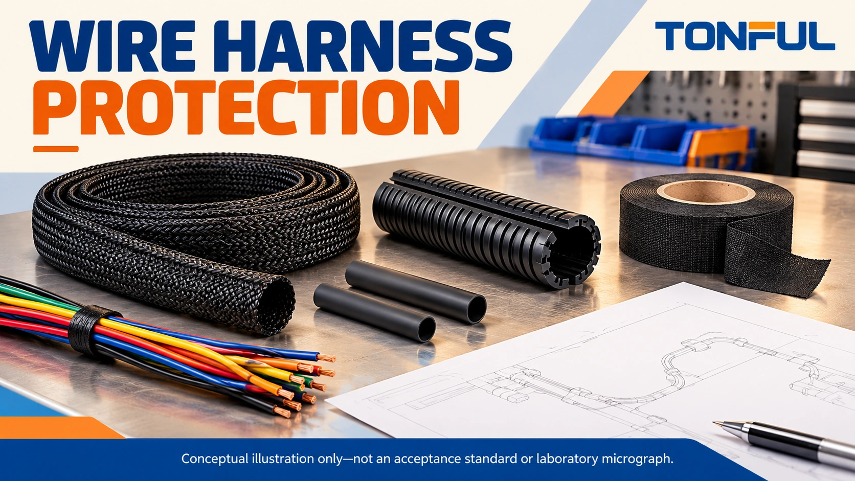
Wire harness protection should address the damage mechanism at each installation zone. A soft covering that prevents trim-panel rattle may not resist a sharp bracket. A corrugated tube may protect a fixed branch yet interfere with a moving joint. A neat tape wrap does not automatically create a waterproof assembly.
Use sleeving, conduit, tape and heat shrink as complementary tools, not interchangeable guarantees. This guide compares their practical roles and explains how to specify installation details, inspect concealed features and validate the completed route. No universal temperature rating, service life or ingress classification is assigned to a material family.
On this page: Exposure map, Method comparison, Installation, Validation, TONFUL enquiry.
Map the Installation Risks
Separate abrasion, heat and movement
Mark the harness route on a controlled drawing and divide it into exposure zones. Identify metal edges, fastener ends, clamp interfaces, moving parts, hot surfaces and accessible service areas. Record whether contact is prohibited or intentionally controlled. Covering a route that continuously rubs an unacceptable edge is not a substitute for correcting the installation geometry.
Distinguish ambient heat, radiant heat and self-heating of loaded conductors. A product’s stated temperature range must be checked against its actual grade and use conditions. Added covering can change heat dissipation; review the installed current duty using the wire gauge selection guide rather than assuming insulation and covering ratings establish assembly ampacity.
Movement needs its own description. State whether the branch is static, moved during maintenance, repeatedly bent or subjected to torsion. Define where bending starts relative to the connector and how supports move. A sleeve’s ability to bend once does not prove a moving harness will survive its required duty.
Include fluids, contamination and access
List actual fluids, cleaning products, dust, UV exposure and moisture conditions where relevant. Separate occasional splash from immersion or pressure washing. Record orientation and possible accumulation points. An open sleeve or split conduit can admit liquid; an enclosed construction can also retain contamination if its openings and drainage are poorly designed.
Identify the service strategy before selecting permanent coverings. Decide whether technicians must inspect individual circuits, replace a branch, remove a connector or access a splice. Specify permitted repair materials and what must be retested after opening the protection. A construction that saves assembly time but makes every service operation destructive may increase total maintenance cost.
Compare the Four Protection Methods
Sleeving and conduit
Braided or woven sleeving can organize conductors and provide application-dependent abrasion protection while accommodating route changes. Continuous and split constructions have different assembly sequences. Check expansion range, final coverage, end treatment and migration on the actual bundle. Do not confuse ordinary polymer sleeving with a conductive EMI shield.
Corrugated conduit provides a defined outer form and may offer useful mechanical separation from surrounding parts. Specify split or closed construction, inner diameter, material grade and fittings. Its slit, end openings and branch exits remain part of the protection boundary. Conduit alone does not remove the need for supports, edge protection or verified sealing.
Tape and heat shrink
Harness tape can secure branches, control noise or provide localized surface protection. Specify backing, adhesive, width, overlap, tension and start/end treatment. Full, spiral and spot wrapping serve different purposes. Do not treat overlap as a universal moisture seal, or assume every electrical tape is suitable for harness noise control and fluid exposure.
Heat shrink can insulate or protect localized transitions when its exact construction suits the geometry. Expanded diameter must pass over the assembly, while recovered dimensions must suit the final section. Adhesive-lined variants require compatible surfaces and a controlled heating process; visible adhesive at an end is not complete evidence of a qualified seal.
TE’s automotive mechanical-protection overview describes heat shrink used for harness, connector and splice protection. Treat it as an application reference, not proof that every tubing grade provides identical abrasion resistance or that a TONFUL assembly has passed those tests.
| Method | Practical role | Main boundary to verify | Service consideration |
|---|---|---|---|
| Braided or woven sleeve | Flexible bundle organization and surface protection | Weave, coverage, ends and abrasion conditions | Split versions may allow lateral access |
| Corrugated conduit | Defined outer routing and mechanical separation | Slit, ends, fittings, stiffness and support | Opening may require replacement restraints |
| Harness tape | Branch retention, localized protection or noise control | Adhesive, overlap, tension and contamination | Removal may disturb labels and insulation |
| Heat shrink | Local insulation, transition protection or specified sealing | Recovery, heating, adhesion and interface geometry | Usually cut off for access and replaced |

The comparison describes potential roles, not a performance ranking. A thin wall, coarse weave or different adhesive can change the outcome within the same category. Request the supplier’s actual part number and relevant data rather than purchasing by appearance. Combining methods may be appropriate, but their interaction still needs review.
Define Installation and Service Controls
Control dimensions and interfaces
Measure minimum and maximum bundle diameter, including splices and transitions. Specify covering length, branch-exit position, overlap and permitted uncovered areas. Account for connector assembly order: a continuous sleeve or shrink tube may need installation before terminal insertion, while a split covering can sometimes be fitted later.
Define clips, clamps and grommets separately. Check interface dimensions, panel thickness, edge orientation and retention evidence. Excessive restraint pressure can deform insulation; insufficient retention allows the harness or covering to migrate. Neither a generic tie count nor an arbitrary clamp interval establishes an acceptable route.
Keep the connector’s mating envelope and latch accessible. Protection should not push against a seal, prevent full engagement or transfer installation load into terminals. Identify the allowed bend region and strain-relief responsibility. The overmolded cable assembly guide explains the separate review of connector-to-cable transitions.
Inspect before concealing features
Check wire identification, terminal seating, splice condition and routing before applying coverings that hide them. Record the inspection stage and acceptance source. Heat-shrink heating must follow product instructions with appropriate equipment, ventilation and protection of nearby components; do not use an uncontrolled flame as a generic installation method.
The manufacturing process guide connects these checks to the assembly sequence. Work instructions should show actual start/end positions and branch details, not merely name a material. Use first-piece verification after changes in covering lot, application tool or process setup where the control plan requires it.

Evaluate cost without inventing savings
Compare material, preparation, application, inspection, tooling and service replacement costs under the same scope. Include consumables used at ends and branches rather than comparing only a price per meter. Installation times should come from a defined production trial, with the same harness revision and trained operators.
Do not assume that one method lasts a fixed number of years or always costs less. A localized sleeve plus separate edge protection may be preferable to covering the entire route. A removable system may justify higher initial cost where frequent inspection is required. Keep engineering acceptance separate from the commercial preference.
Validate and Document the Protected Harness
Test the damage mechanism
Choose tests from the approved application requirements. Abrasion evaluation needs the specified contact geometry, pressure, movement and failure criterion. Crush or impact checks need their own fixture and direction. Flex testing should use representative routing, restraints and motion; a material coupon does not establish the performance of the installed branch.
For fluids or cleaning exposure, identify the agent, concentration, temperature, duration and recovery period. Review dimensional change, adhesion, cracking and relevant electrical results afterward. Sealing evaluation must identify the complete test boundary and installation condition. Do not assign an IP rating from a photograph of tubing or a splash demonstration.
Define sample quantity, allocation, conditioning and test order. State whether destructive inspections use separate specimens or follow environmental testing. Record instrument range, accuracy and calibration where acceptance depends on measurement. A replacement specimen or invalid test needs a documented reason and authorized disposition, not a silent restart.
Copyable protection record
Inspect the prototype inside its representative installation, not only flat on a board. Close covers, move adjacent mechanisms and reproduce the intended service access without energizing an unsafe system. Look for squeezed branches, sleeve bunching, exposed ends and contact introduced by the added covering. Photograph the observed position against the drawing reference before making adjustments. If a technician must remove a restraint to reach a connector, include that operation in the service trial. Record whether the covering can be restored consistently and whether the original electrical and mechanical checks remain accessible. These observations often reveal installation problems that a standalone material test cannot reproduce.
| Record field | Required entry |
|---|---|
| Harness zone | Drawing revision, location and branch identity |
| Exposure | Contact, heat, motion, fluids, UV and moisture conditions |
| Covering | Exact part, grade, dimensions and lot |
| Installation | Length, overlaps, ends, exits and assembly sequence |
| Support | Clip or clamp identity, interface and retention source |
| Hidden features | Inspection stage, evidence ID and inspector |
| Validation | Samples, fixture, conditions, results and limit source |
| Service method | Removal, replacement and required reinspection |
| Approval | Owner, decision, deviations and review date |

If an abrasion result fails, preserve the contact location and covering orientation before disassembly. Determine whether the cause is unsuitable material, migration, excessive contact or a route error. Correct the responsible feature and update the drawing or process instruction. The harness continuity testing guide supports electrical rechecks, but a passing circuit alone cannot prove mechanical protection is adequate.
Work With TONFUL on a Zone-Based Protection Plan
Share your route drawing, bundle dimensions, motion, exposure conditions and service expectations through TONFUL’s project enquiry channel. Request an exact material proposal and clarify the inspection and validation evidence needed before sample approval.
Approve protection by zone and function rather than by a broad “heavy-duty” label. Keep material substitutions, added coverings and support changes under review, because each can affect thermal behavior, clearance and accessibility. Release the construction that was evaluated, with its defined limits and maintenance method.