A production line stops. The motor pulley has slipped on its shaft—again. The maintenance team discovers the culprit: a flat point set screw installed where a cup point was specified. The shaft surface shows no indentation, no bite, just polished wear marks where friction alone couldn’t hold under cyclic torque. This single fastener choice cost the facility four hours of downtime and $12,000 in lost production. The engineering lesson? Set screw point geometry is not interchangeable, and selecting the wrong type creates a predictable failure mode that most procurement teams overlook until it’s too late.
Set screws—also called grub screws—are headless threaded fasteners that secure components to shafts, rods, or housings through direct contact pressure rather than through-hole clamping. Unlike bolts that rely on nut tension, set screws transmit holding force through their point geometry, making point type selection the single most critical specification decision. This guide provides electrical engineers, maintenance technicians, and B2B procurement managers with the technical data needed to specify cup point versus flat point set screws correctly, covering contact mechanics, holding power differentials, material compatibility, international standards (DIN 913-916, ISO 4026-4029), and installation protocols that prevent the failure modes seen in high-vibration industrial environments.

What Are Set Screws and Why Point Type Matters
A set screw is a fully threaded fastener without a protruding head, designed to secure one component against or within another through point contact pressure. The hex socket (Allen drive) sits flush or countersunk with the outer surface, making set screws ideal for rotating assemblies where head protrusion would create interference or safety hazards. Common applications include shaft collars, pulleys, gears, motor couplings, linear motion components, and automotive electrical connectors where space constraints demand low-profile fastening solutions.
The point—the business end that contacts the shaft or mating surface—determines how the set screw generates holding power. Cup points create a circular indentation that bites into the shaft surface, establishing mechanical interlock. Flat points distribute pressure across a broader contact patch, relying primarily on friction with minimal surface penetration. Cone points drive a sharp wedge into softer materials for maximum bite. Dog points locate into pre-drilled holes or machined flats for positive angular alignment. Each geometry produces different contact stress distributions, holding torque capacities, and shaft surface effects that make point type selection application-specific rather than interchangeable.
Mismatched point selection creates three failure modes: insufficient holding power (flat point on hardened shaft under high torque), excessive shaft damage (cone point on precision ground shaft requiring rework), and vibration-induced loosening (any point type without proper torque or thread locking compound in dynamic applications). Understanding the mechanical trade-offs between cup and flat points—the two most common industrial types—prevents these failures and optimizes fastener performance across electrical assemblies, motor drives, and precision instrumentation.
Cup Point vs. Flat Point: Contact Mechanics and Holding Power
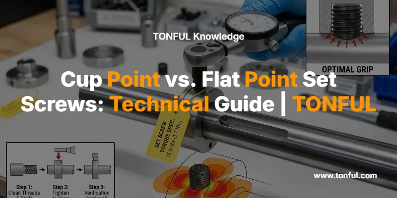
Cup point and flat point set screws represent opposite ends of the holding-power-versus-shaft-preservation spectrum. Cup points (DIN 916 / ISO 4029) feature a concave hemispherical cavity at the tip that concentrates contact pressure along a circular edge. When torqued, this edge plastically deforms the shaft surface, creating a ring-shaped indentation approximately 0.1-0.3mm deep depending on shaft hardness and installation torque. This mechanical bite provides the baseline holding power index of 1.0 against which all other point types are compared. The indentation resists both rotational and axial displacement, making cup points the default choice for general-purpose shaft mounting where surface marking is acceptable and the shaft will not slide past the indentation during assembly or service.
Flat point set screws (DIN 913 / ISO 4026) have a completely flat tip with no protruding geometry. The contact patch is larger than cup point’s ring edge, distributing the same clamping force over greater area and reducing contact stress. This produces minimal shaft penetration—typically just burnishing rather than permanent deformation on hardened steel shafts. The trade-off is reduced holding power: flat points achieve approximately 0.92 times the torsional holding capacity of cup points under identical installation torque, a 8% reduction that becomes significant in high-torque or high-vibration applications. Flat points are specified when shaft surface preservation is mandatory—precision ground shafts, shafts requiring frequent repositioning, shafts that must slide through multiple set screw locations during assembly, or soft materials (aluminum, brass) where cup point bite would create excessive deformation.

The contact mechanics difference becomes critical in three scenarios. First, in rotating machinery with cyclic loading (motor shafts, conveyor drives, pump couplings), the cup point’s mechanical interlock resists fretting and micro-slip better than flat point’s friction-only hold. Field studies show cup points maintain 85-90% of initial holding torque after 10⁶ load cycles, while flat points drop to 70-75% without thread locking compound. Second, on soft shaft materials (aluminum alloys, brass, plastics), cup points can over-penetrate and create stress risers that initiate fatigue cracks; flat points are mandatory here, with installation torque reduced 30-40% below steel-shaft values. Third, in precision positioning applications (linear motion assemblies, optical mounts, instrumentation), flat points allow micro-adjustment without creating new indentations each time the component is repositioned.
Complete Set Screw Point Type Comparison
While cup and flat points dominate industrial usage, three additional point types serve specialized applications where their unique geometries solve specific engineering problems.
| Point Type | Standard | Holding Power Index | Shaft Damage | Primary Applications | Key Advantage |
|---|---|---|---|---|---|
| Cup Point | DIN 916 / ISO 4029 | 1.00 (baseline) | Moderate (0.1-0.3mm circular indentation) | General-purpose shaft mounting, pulleys, collars, gears | Best balance of holding power and availability |
| Flat Point | DIN 913 / ISO 4026 | 0.92 | Minimal (burnishing only) | Soft shafts (Al, brass), precision ground surfaces, frequent repositioning | Preserves shaft surface integrity |
| Cone Point | DIN 914 / ISO 4027 | 1.07 | High (deep wedge penetration) | Permanent installations, soft materials, maximum bite required | Highest torsional holding power |
| Dog Point | DIN 915 / ISO 4028 | 0.92 | None (locates in hole) | Angular alignment, pre-drilled flats, splined shafts | Positive location without shaft deformation |
| Knurled Cup | Non-standard | 1.05-1.10 | High (serrated bite) | High-vibration environments, locking action required | Serrations resist loosening under vibration |
Cone point set screws feature a sharp 90° or 118° conical tip that wedges into the shaft surface, achieving 1.07 times cup point holding power—the highest of any standard point type. The concentrated point stress creates deep penetration (0.3-0.5mm) that provides excellent resistance to rotational slip, making cone points ideal for permanent installations where disassembly is rare and shaft surface damage is acceptable. However, the deep indentation can interfere with bearing installation if the bearing must slide over the set screw location, and the sharp point can create stress concentration that reduces shaft fatigue life in high-cycle applications. Cone points are commonly specified for securing gears and sprockets to shafts in low-speed, high-torque applications where the shaft will not be repositioned.
Dog point set screws have a cylindrical extension (the “dog”) with a flat tip, available in half-dog (short) and full-dog (long) configurations depending on screw length per DIN 915 / ISO 4028. Rather than biting into the shaft surface, the dog locates into a pre-drilled hole, milled flat, or spline groove, providing positive angular alignment without creating shaft deformation. This makes dog points the preferred choice for precision assemblies requiring repeatable angular positioning—indexing mechanisms, encoder mounts, and keyed shaft alternatives. The dog diameter is held to tight tolerances (±0.05mm typical) to ensure proper fit in the mating feature. Dog points achieve 0.92 holding power index because they rely on shear strength of the dog rather than friction or bite, but they provide superior resistance to angular displacement compared to cup or flat points.
Knurled cup point set screws combine cup point geometry with a serrated or knurled edge that creates multiple small teeth around the contact rim. The serrations bite into the shaft surface more aggressively than smooth cup points, increasing holding power to 1.05-1.10 times baseline and providing a mechanical locking action similar to serrated lock washers. This makes knurled cup points valuable in high-vibration environments—automotive combination switches, off-road vehicle assemblies, and industrial equipment subject to shock loading—where standard cup points may work loose over time. The trade-off is more severe shaft damage and difficulty removing the screw without damaging the shaft surface, limiting knurled cup points to applications where permanent installation or infrequent service is acceptable.

Material Selection and Shaft Compatibility
Set screw material must be matched to shaft material and application environment to prevent galling, corrosion, or inadequate hardness differential. The standard material for industrial set screws is alloy steel heat-treated to 45H hardness (approximately HRC 45-53) per DIN/ISO specifications, providing the strength needed to bite into typical steel shafts (HRC 20-40) without thread stripping. This 10-15 Rockwell C point hardness differential ensures the set screw point deforms the shaft rather than the shaft deforming the screw, which would eliminate holding power.
Stainless steel set screws (A2-70 or A4-80 grades) are specified for corrosive environments—marine applications, food processing equipment, chemical plants, and outdoor installations where carbon steel would rust. However, stainless-on-stainless installations create galling risk: when stainless threads rub under high pressure, microscopic cold welding can seize the fastener. Prevention strategies include using anti-seize compound during installation, reducing installation torque by 15-20%, or specifying cup point geometry (which reduces thread friction compared to cone point’s higher insertion resistance). For marine electrical wiring and waterproof connector assemblies, stainless set screws prevent the corrosion-induced loosening that compromises electrical connections in salt spray environments.
Brass and nylon-tipped set screws are used when shaft preservation is paramount and holding power requirements are modest. Brass set screws (often with flat or oval points) are common in precision instruments, optical equipment, and decorative hardware where even the minimal marking from steel flat points is unacceptable. Nylon-tipped set screws use a plastic insert at the point to provide vibration damping and eliminate metal-to-metal contact, preventing galvanic corrosion in dissimilar-metal assemblies (stainless shaft with aluminum housing). These soft-point screws achieve only 0.5-0.6 holding power index and require 30-40% torque reduction, limiting them to low-torque, low-vibration applications.
When securing components to aluminum or brass shafts, material hardness reverses the normal relationship: the set screw is harder than the shaft. Cup and cone points will over-penetrate, creating deep gouges that act as stress concentrations and can initiate fatigue cracks. Flat point or oval point set screws are mandatory, with installation torque reduced 30-40% below the values used for steel shafts. For example, an M6 cup point set screw might be torqued to 5.0 Nm on a steel shaft but must be limited to 3.0-3.5 Nm on an aluminum shaft with flat point geometry. This reduced torque often necessitates using two set screws at 90° orientation or adding thread locking compound to achieve adequate holding power without shaft damage.

Standards and Specifications: DIN vs. ISO
Set screw dimensions, tolerances, and mechanical properties are governed by parallel DIN (German) and ISO (International) standards that are functionally equivalent in modern practice, though the DIN designations remain more common in industrial catalogs and engineering drawings.
- DIN 913 / ISO 4026: Hexagon socket set screws with flat point
- DIN 914 / ISO 4027: Hexagon socket set screws with cone point
- DIN 915 / ISO 4028: Hexagon socket set screws with dog point (half-dog or full-dog depending on length)
- DIN 916 / ISO 4029: Hexagon socket set screws with cup point
The ISO standards omit certain nominal diameters (M1.4, M1.8, M14, M18, M22) that were included in the original DIN specifications, making these sizes progressively uncommon as DIN standards have been formally withdrawn in favor of ISO harmonization. For procurement purposes, specifying either DIN or ISO designation will yield the same fastener from most suppliers, though ISO designations are preferred for new designs to ensure long-term availability.
Both standards specify 45H alloy steel as the default material (quenched and tempered to HRC 45-53 core hardness) for sizes M3 through M24, with stainless steel grades (A2, A4) available as alternates. Thread tolerances follow ISO 965-1 class 6g for external threads, providing free-running fit in standard tapped holes. Socket size follows ISO 4762 hexagon socket dimensions—for example, M6 set screws use a 5mm hex socket, M8 use 6mm, M10 use 8mm—ensuring compatibility with standard hex key sets used across electrical tool kits and automotive maintenance equipment.
Point Type Selection Guide by Application
Selecting the optimal set screw point type requires matching contact mechanics to shaft material, service conditions, and assembly requirements. This decision matrix provides specification guidance for common industrial and electrical applications.
| Application Type | Shaft Material | Recommended Point | Rationale |
|---|---|---|---|
| Motor shaft collars, pulleys (permanent) | Steel, HRC 20-40 | Cup point (DIN 916) | Standard holding power, acceptable surface marking, general-purpose |
| Precision ground shafts (optical, instrumentation) | Steel, HRC 40-50 | Flat point (DIN 913) | Preserves surface finish, allows repositioning without new indentations |
| High-vibration machinery (pumps, compressors) | Steel | Knurled cup point | Serrated edge resists loosening, mechanical locking action |
| Aluminum housings, soft shafts | Aluminum, brass | Flat point, 30-40% reduced torque | Prevents over-penetration and stress concentration |
| Gear/sprocket permanent mounting | Steel | Cone point (DIN 914) | Maximum holding power for high-torque applications |
| Angular indexing, repeatable positioning | Steel with milled flat | Dog point (DIN 915) | Positive location in pre-drilled hole or flat, no shaft deformation |
| Frequent adjustment/repositioning | Any | Flat point or oval point | Minimal surface damage allows multiple repositionings |
| Corrosive environments (marine, chemical) | Stainless steel | Stainless cup point with anti-seize | Prevents rust-induced loosening, anti-seize prevents galling |
For automotive wire harness assemblies and electrical connector mounting, set screws secure strain relief components, cable glands, and connector backshells to support structures. These applications typically use M3-M6 stainless steel cup point set screws with medium-strength thread locking compound (Loctite 243 equivalent) to prevent vibration-induced loosening while allowing disassembly for service. The cup point provides adequate holding power in the low-torque environment (typically 1.5-3.0 Nm installation torque) while the stainless material prevents corrosion in engine bay and underbody locations exposed to moisture and road salt.
Installation Best Practices and Torque Specifications
Proper set screw installation requires attention to shaft preparation, torque control, and thread locking to achieve design holding power and prevent premature loosening. The installation sequence differs from standard bolt tightening because set screws generate holding force through point contact rather than thread tension.
Shaft preparation: For cup and cone points, the shaft surface should be clean, dry, and free of oil or cutting fluid that would reduce friction. Light surface rust or mill scale actually improves bite by providing a rougher contact surface. For dog points, the locating hole or flat must be machined to tight tolerances (±0.05mm position, ±0.02mm depth) and deburred to ensure the dog seats fully without interference. Precision ground shafts intended for flat point set screws should be wiped with solvent to remove any residual grinding compound that could act as a lubricant and reduce holding power.
Torque specifications: Unlike bolts where torque creates clamp load through thread tension, set screw torque drives the point into the shaft surface to create the mechanical interlock or friction hold. Recommended installation torques for standard 45H alloy steel set screws in steel shafts (dry assembly, no lubricant):
| Screw Size | Cup/Flat/Dog Point Torque | Cone Point Torque | Hex Key Size |
|---|---|---|---|
| M3 | 1.2 Nm (10.6 in-lb) | 1.0 Nm (8.8 in-lb) | 2.0 mm |
| M4 | 2.5 Nm (22 in-lb) | 2.0 Nm (17.7 in-lb) | 2.5 mm |
| M5 | 4.0 Nm (35 in-lb) | 3.5 Nm (31 in-lb) | 3.0 mm |
| M6 | 7.0 Nm (62 in-lb) | 6.0 Nm (53 in-lb) | 4.0 mm |
| M8 | 14.0 Nm (124 in-lb) | 12.0 Nm (106 in-lb) | 5.0 mm |
| M10 | 27.0 Nm (239 in-lb) | 23.0 Nm (204 in-lb) | 6.0 mm |

These values assume dry conditions and steel-on-steel contact. Reduce torque by 30-40% for aluminum or brass shafts. Reduce by 15-20% when using thread locking compound, which adds chemical adhesion to mechanical holding power. For critical applications, use a torque wrench or torque-limiting hex key rather than a standard L-key to ensure consistent installation torque across multiple fasteners.
Thread engagement: Set screws should engage a minimum of 1.5 times the screw diameter into the tapped hole to prevent thread stripping under load. For M6 screws, this means at least 9mm of thread engagement; for M8, at least 12mm. Shallow tapped holes are a common failure mode in cast aluminum housings where the designer specified insufficient wall thickness for proper thread depth. When thread engagement is marginal, consider using a threaded insert (HeliCoil or similar) to provide full-strength threads in soft materials.
Thread locking compound: Medium-strength anaerobic thread locker (Loctite 243, Vibra-Tite VC-3, or equivalent) is recommended for all set screws in vibration-prone applications—motor mounts, vehicle assemblies, machinery subject to shock loading. Apply a small drop to the threads before installation; the compound cures in the absence of air once the screw is seated, creating a polymer lock that prevents vibration-induced backing-out while still allowing disassembly with hand tools. High-strength thread lockers (Loctite 271) should be avoided unless permanent installation is required, as they may necessitate heat application for removal and can make field service difficult.
Multiple set screw orientation: When using two or more set screws to secure a single component (common practice for shaft collars and large pulleys), position them 90° apart rather than 180° opposed. The 90° orientation creates a more balanced clamping force distribution and reduces the tendency for the component to cock on the shaft. Tighten set screws in a star pattern (alternating between screws) rather than sequentially to equalize contact pressure and prevent the component from shifting during installation.
Common Failure Modes and Prevention
Set screw failures fall into three categories: insufficient holding power leading to component slip, excessive shaft damage causing stress concentration or assembly interference, and vibration-induced loosening. Each failure mode has identifiable root causes and engineering solutions.
Slip failure occurs when the set screw cannot generate enough holding force to resist applied torque or axial load. Root causes include: wrong point type (flat point specified where cup point needed), insufficient installation torque (hand-tightened rather than torqued to specification), hardness mismatch (set screw softer than shaft, causing point deformation rather than shaft bite), or oil contamination reducing friction. The fix is straightforward: specify cup or cone point for maximum holding power, verify installation torque with a torque wrench, ensure 10-15 HRC hardness differential between screw and shaft, and clean shaft surfaces before assembly. For borderline cases, add a second set screw at 90° or mill a shallow flat on the shaft to increase contact area.
Shaft damage failure manifests as stress risers that initiate fatigue cracks, interference with bearing installation, or excessive deformation in soft materials. This occurs when cone points are used on precision shafts, cup points are over-torqued on aluminum, or set screws are repositioned multiple times creating multiple indentations. Prevention requires matching point type to shaft material (flat point for soft or precision shafts), reducing torque for soft materials, and using dog points in pre-drilled holes when frequent repositioning is required. For shafts that must slide through set screw locations during assembly (motor shafts passing through multiple bearings before the pulley is installed), specify flat points and position set screw holes in locations where the shaft will not slide past after final assembly.
Vibration loosening is the most common field failure mode, where set screws back out over time in high-vibration environments despite adequate initial torque. The mechanism is micro-slip at the thread interface under cyclic loading, which incrementally rotates the screw counterclockwise. Prevention strategies include: medium-strength thread locking compound (mandatory for automotive and machinery applications), knurled cup points whose serrations provide mechanical locking, lock wire or set screw locking patches for critical assemblies, and periodic re-torquing during scheduled maintenance intervals. For heavy-duty truck combination switches and automotive terminals, vibration-resistant set screw installations are critical to maintaining electrical connection integrity over the vehicle service life.
Frequently Asked Questions
What is the difference between cup point and flat point set screws?
Cup point set screws have a concave hemispherical cavity at the tip that creates a circular edge contact, which bites into the shaft surface and creates a 0.1-0.3mm indentation for mechanical holding power. Flat point set screws have a completely flat tip that distributes pressure over a larger contact area, producing minimal shaft penetration (burnishing only) but 8% lower holding power (0.92 vs. 1.0 index). Cup points are the general-purpose choice for steel shafts where surface marking is acceptable; flat points are specified when shaft surface preservation is critical or when frequent repositioning is required.
When should I use a flat point instead of a cup point?
Use flat point set screws in four scenarios: (1) precision ground shafts where surface finish must be preserved (optical equipment, instrumentation, bearing journals), (2) soft shaft materials (aluminum, brass, plastics) where cup point penetration would create excessive deformation or stress concentration, (3) applications requiring frequent adjustment or repositioning where multiple cup point indentations would damage the shaft, and (4) shafts that must slide through the set screw location during assembly (motor shafts passing through bearings before pulley installation). Flat points rely on friction rather than mechanical bite, so consider using two screws at 90° or adding thread locking compound to compensate for the reduced holding power.
What torque should I use for set screws?
Installation torque depends on screw size and shaft material. For standard M6 cup point set screws in steel shafts, use 7.0 Nm (62 in-lb); M8 requires 14.0 Nm (124 in-lb); M10 requires 27.0 Nm (239 in-lb). Reduce these values by 30-40% for aluminum or brass shafts to prevent over-penetration. Reduce by 15-20% when using thread locking compound. Cone points require 10-15% less torque than cup points because their sharp geometry concentrates stress more effectively. Always use a torque wrench or calibrated hex key for critical applications rather than estimating torque by feel, as under-torquing causes slip failures while over-torquing can strip threads in soft materials or break small-diameter screws.
Can set screws be reused?
Set screws can be reused if the threads are undamaged and the point geometry remains intact, but reuse reduces reliability in critical applications. Each installation cycle work-hardens the point slightly and may deform it, reducing bite effectiveness on subsequent installations. Inspect threads for galling, cross-threading, or thread locking compound residue; clean threads with a wire brush and solvent before reuse. Inspect the point for mushrooming, chipping, or excessive wear; discard screws with visible point damage. For non-critical applications (laboratory equipment, prototypes, low-torque assemblies), reuse is acceptable. For production assemblies, high-vibration environments, or safety-critical applications (automotive brake systems, lifting equipment, medical devices), use new set screws and fresh thread locking compound to ensure design holding power and prevent field failures.
What is the difference between DIN and ISO set screw standards?
DIN (German) and ISO (International) set screw standards are functionally equivalent and interchangeable in modern practice. DIN 913 = ISO 4026 (flat point), DIN 914 = ISO 4027 (cone point), DIN 915 = ISO 4028 (dog point), DIN 916 = ISO 4029 (cup point). The ISO standards omit certain nominal diameters (M1.4, M1.8, M14, M18, M22) that were included in DIN specifications, making these sizes less common. Both standards specify the same thread tolerances (ISO 965-1 class 6g), socket sizes (ISO 4762), and material grades (45H alloy steel, A2/A4 stainless). For procurement, either designation will yield the same fastener from most suppliers, though ISO designations are preferred for new designs to ensure long-term international availability.
How do I prevent set screws from loosening in high-vibration applications?
Vibration-induced loosening is prevented through four strategies used in combination: (1) Apply medium-strength anaerobic thread locking compound (Loctite 243 equivalent) to threads before installation—this creates a polymer lock that prevents micro-rotation while allowing disassembly with hand tools. (2) Specify knurled cup point set screws whose serrated edge provides mechanical locking action similar to lock washers. (3) Use two set screws positioned 90° apart to balance clamping forces and create redundancy. (4) Implement periodic re-torquing during scheduled maintenance intervals (every 500-1000 operating hours for critical assemblies). For extreme vibration environments (off-road vehicles, impact tools, reciprocating machinery), consider dog point set screws in pre-drilled holes, which provide positive mechanical location that cannot back out, or switch to alternative fastening methods such as pinned collars or keyed shafts.
Conclusion: Specifying Set Screws for Reliable Fastening
Set screw point type selection directly determines holding power, shaft surface effects, and long-term reliability in mechanical and electrical assemblies. Cup points provide the baseline holding power (index 1.0) and represent the general-purpose choice for steel shafts where surface marking is acceptable. Flat points sacrifice 8% of holding power to preserve shaft surface integrity, making them mandatory for precision ground surfaces, soft materials (aluminum, brass), and applications requiring frequent repositioning. Cone points deliver maximum holding power (index 1.07) for permanent installations, while dog points provide positive angular location without shaft deformation, and knurled cup points resist vibration-induced loosening through serrated mechanical locking.
Material compatibility requires matching set screw hardness to shaft material—45H alloy steel for standard steel shafts, stainless grades for corrosive environments, and reduced installation torque (30-40% reduction) for aluminum or brass. International standards DIN 913-916 and ISO 4026-4029 ensure dimensional consistency and mechanical properties across global supply chains. Proper installation demands torque control (use calibrated tools, not hand-feel estimation), adequate thread engagement (minimum 1.5× diameter), thread locking compound for vibration resistance, and 90° positioning for multiple-screw installations.
The production line failure described in the opening—flat point slip on a motor pulley—illustrates the cost of incorrect specification: $12,000 in downtime from a $0.15 fastener. The engineering solution is straightforward: cup point set screws torqued to 14.0 Nm with medium-strength thread locker would have provided the mechanical bite and vibration resistance needed for reliable service. For B2B procurement teams specifying fasteners across electrical connector assemblies, wire harness components, and automotive electrical systems, understanding cup versus flat point mechanics prevents field failures and optimizes total cost of ownership.
TONFUL Electric manufactures precision electrical components and fastening solutions for industrial, automotive, and OEM applications. Our engineering team provides technical support for component selection, custom assembly solutions, and bulk procurement programs. For set screw specifications, terminal and connector assemblies, or electrical tool kits tailored to your application requirements, contact our B2B sales team for technical consultation and volume pricing.
