When specifying heat shrink tubing for electrical installations, the shrink ratio is the single most critical parameter that determines whether your application will achieve reliable insulation, environmental sealing, and long-term performance. Yet this specification remains widely misunderstood, leading to costly installation failures, inadequate sealing, and premature component degradation.
This comprehensive engineering guide explains the technical fundamentals of 2:1, 3:1, and 4:1 heat shrink ratios, providing electrical engineers, procurement managers, and installation technicians with the data-driven insights needed to specify the correct tubing for demanding applications.
What Is Heat Shrink Ratio?
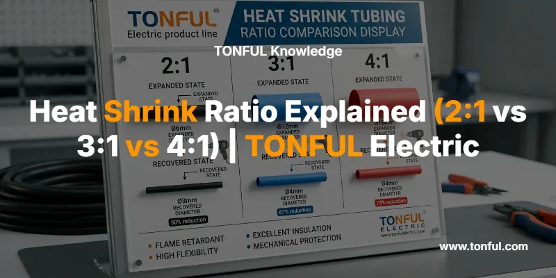
The heat shrink ratio represents the mathematical relationship between a tube’s expanded (as-supplied) inner diameter and its fully recovered (shrunken) inner diameter after heat application. This ratio determines the range of substrate diameters a single tube size can accommodate and the tightness of the final seal.
The ratio is expressed as expanded diameter : recovered diameter. For example, a 2:1 ratio means the tubing supplied diameter is twice the size of its recovered diameter after heating. If you purchase 12mm diameter tubing with a 2:1 ratio, it will shrink down to 6mm once heat is applied.
The Three Standard Shrink Ratios
| Shrink Ratio | Shrinkage Percentage | Recovered Diameter | Typical Expanded Size Example | Recovered Size Example |
|---|---|---|---|---|
| 2:1 | 50% | Half of original | Φ10mm | Φ5mm |
| 3:1 | 67% | One-third of original | Φ24mm | Φ8mm |
| 4:1 | 75% | One-quarter of original | Φ32mm | Φ8mm |
Understanding this relationship is essential because the ratio directly impacts four critical performance factors: conformability to irregular shapes, sealing effectiveness, substrate accommodation range, and installation complexity.

2:1 Heat Shrink Ratio: The Industry Standard
The 2:1 shrink ratio is the most widely specified configuration in electrical and mechanical applications, accounting for approximately 70% of industrial heat shrink tubing consumption. This ratio shrinks to exactly half its original diameter, providing a 50% reduction in size.
Technical Specifications
- Shrinkage: 50% diameter reduction
- Accommodation Range: Narrow (best for uniform diameters)
- Longitudinal Shrinkage: 5-8% length reduction
- Cost Factor: Most economical option
- Recovery Temperature: Typically 90-120°C depending on material
Primary Applications
The 2:1 ratio excels in applications involving consistent, uniform substrate diameters:
- General wire insulation for building wiring and control panels
- Cable bundling and harnessing in automotive and industrial systems
- Strain relief for uniform cable assemblies
- Color-coded wire identification in electrical panels
- Basic environmental protection for indoor installations
When working with heat shrink terminals, 2:1 tubing provides adequate coverage for standard crimp connections where the barrel diameter closely matches the wire insulation diameter.
Limitations
Because 2:1 tubing only contracts by half, it cannot accommodate significant diameter variations. A 2:1 tube sized to fit over a large connector body will remain loose on the adjacent smaller-diameter wire, compromising the seal. For applications involving connectors, solder joints, or irregular geometries, higher ratios become necessary.
3:1 Heat Shrink Ratio: The Versatile Middle Ground
The 3:1 shrink ratio contracts to one-third of its original diameter, providing 67% shrinkage. This increased contraction range makes 3:1 tubing the preferred choice for applications involving moderate diameter transitions and irregular substrate shapes.
Technical Specifications
- Shrinkage: 67% diameter reduction
- Accommodation Range: Wide (handles 3× diameter variation)
- Longitudinal Shrinkage: 8-12% length reduction
- Cost Factor: 15-25% premium over 2:1
- Recovery Temperature: 90-130°C depending on material
Primary Applications
The 3:1 ratio is engineered for applications requiring conformability and diameter flexibility:
- Wire terminations and splices with connector bodies
- Heat shrink terminals where crimp barrels create diameter steps
- Solder joint protection in electronic assemblies
- Irregular substrate geometries such as molded connectors
- Marine and outdoor applications requiring enhanced sealing
- Automotive electrical connectors with varying diameters
When paired with adhesive lining (dual-wall construction), 3:1 tubing creates waterproof, environmentally sealed connections suitable for marine-grade applications and underground installations.
Engineering Advantages
The wider accommodation range of 3:1 tubing reduces inventory complexity. A single 3:1 tube size can often replace two or three different 2:1 sizes, simplifying procurement and reducing stock-keeping requirements for maintenance operations and field service teams.

4:1 Heat Shrink Ratio: Maximum Conformability
The 4:1 shrink ratio represents the highest common shrinkage specification, contracting to one-quarter (25%) of its original diameter. This extreme contraction capability enables a single tube to accommodate substrate diameter variations of 4:1 or greater.
Technical Specifications
- Shrinkage: 75% diameter reduction
- Accommodation Range: Very wide (handles 4× diameter variation)
- Longitudinal Shrinkage: 10-15% length reduction
- Cost Factor: 30-50% premium over 2:1
- Recovery Temperature: 100-135°C depending on material
Primary Applications
The 4:1 ratio is specified for the most demanding applications:
- Large automotive connectors with substantial diameter transitions
- Environmental sealing of cable entries and penetrations
- Harsh environment protection in industrial and off-road equipment
- Repair sleeves for damaged cable jackets
- Military and aerospace applications requiring maximum reliability
- High-temperature automotive applications in engine compartments
Inventory Optimization
While 4:1 tubing carries a higher unit cost, the wide accommodation range can reduce total inventory investment. A single 4:1 tube size may replace four different 2:1 sizes, significantly simplifying procurement for electrical component manufacturers and reducing warehouse space requirements.
Installation Considerations
The greater shrinkage of 4:1 tubing requires more careful positioning during installation. The 10-15% longitudinal shrinkage means technicians must account for length reduction when covering specific connector sections. Proper heat shrink tubing sizing calculations become critical to avoid exposing adjacent areas after recovery.

Heat Shrink Ratio Selection Guide
Selecting the optimal shrink ratio requires systematic analysis of five critical application parameters:
1. Substrate Diameter Analysis
Measure both the maximum diameter the tubing must fit over (before shrinking) and the minimum diameter it must grip (after recovery):
Selection Formula:
- Expanded inner diameter should exceed maximum substrate diameter by 20-30%
- Recovered diameter should be 75-80% of minimum grip diameter
Example Calculation: For a connector assembly with a 15mm body transitioning to 6mm wire:
- Maximum diameter: 15mm
- Minimum diameter: 6mm
- Diameter ratio: 15 ÷ 6 = 2.5:1
Recommended ratio: 3:1 (provides adequate range with safety margin)
2. Environmental Conditions
| Environment | Minimum Recommended Ratio | Additional Requirements |
|---|---|---|
| Indoor, dry | 2:1 | Standard single-wall |
| Outdoor, occasional moisture | 2:1 or 3:1 | UV-resistant material |
| Marine, continuous moisture | 3:1 | Adhesive-lined dual-wall |
| Underground, buried | 3:1 or 4:1 | Heavy-wall adhesive-lined |
| Harsh industrial, chemical exposure | 4:1 | Chemical-resistant material |
3. Mechanical Stress Factors
Applications subject to vibration, flexing, or abrasion—such as automotive underhood wiring or industrial machinery—benefit from 3:1 or 4:1 heavy-wall tubing. The increased material thickness resists cut-through and provides superior strain relief.
4. Installation Constraints
Confined spaces may limit heat gun access, favoring thinner 2:1 tubing that recovers quickly with less heat input. Conversely, field installations in challenging environments justify the enhanced sealing of higher ratios despite longer installation time.
5. Cost-Performance Balance
| Ratio | Unit Cost Index | Inventory Complexity | Best Use Case |
|---|---|---|---|
| 2:1 | 1.0× (baseline) | High (more sizes needed) | High-volume uniform applications |
| 3:1 | 1.2-1.3× | Medium | General-purpose with diameter variation |
| 4:1 | 1.4-1.6× | Low (fewer sizes needed) | Extreme diameter variation or harsh environments |

Material Considerations and Temperature Ratings
The base material of heat shrink tubing interacts with shrink ratio to determine overall performance characteristics:
Common Material Types
| Material | Temperature Range | Typical Ratios | Primary Applications |
|---|---|---|---|
| Polyolefin | -55°C to 125°C | 2:1, 3:1, 4:1 | General electrical, most common |
| PVC | -20°C to 105°C | 2:1 | Economy applications, limited flexibility |
| Fluoropolymer (PTFE) | -67°C to 260°C | 2:1, 4:1 | Aerospace, chemical processing |
| Silicone | -65°C to 200°C | 2:1, 3:1 | High flexibility, vibration dampening |
| Neoprene | -40°C to 150°C | 3:1, 4:1 | Irregular shapes, maximum conformability |
Polyolefin vs PVC heat shrink tubing represents the most common material selection decision, with polyolefin offering superior flexibility, wider temperature range, and better long-term aging characteristics.
Voltage and Flame Ratings
- Standard voltage rating: 600V for most applications
- High-voltage busbar tubing: 1KV, 10KV, 35KV ratings available
- Flame retardant grade: VW-1 standard (self-extinguishing within 60 seconds)
- Military specifications: MIL-DTL-23053 for aerospace and defense applications
The 80:20 Rule for Heat Shrink Selection
Professional engineers apply the 80:20 rule when specifying heat shrink tubing: the tubing should shrink by a maximum of 80% of its shrink ratio capability and a minimum of 20%. This guideline ensures reliable recovery without overstressing the material or leaving excessive slack.
Practical Application: For a 3:1 tube with 12mm expanded diameter:
- Maximum recommended substrate: 12mm × 0.80 = 9.6mm
- Minimum recommended substrate: 12mm ÷ 3 × 1.20 = 4.8mm
Operating within this range ensures optimal wall thickness, mechanical strength, and sealing performance after recovery.

Common Selection Mistakes and How to Avoid Them
Mistake 1: Ignoring Longitudinal Shrinkage
Many technicians account for radial shrinkage but forget that heat shrink tubing also contracts lengthwise. This oversight leads to exposed areas after installation.
Solution: Add 15-20% extra length for 4:1 tubing, 10-15% for 3:1, and 8-10% for 2:1 when cutting tubing to length.
Mistake 2: Wrong Ratio for Application Complexity
Specifying 2:1 tubing for applications with significant diameter transitions results in loose fits and compromised sealing. Conversely, using 4:1 tubing for simple uniform wires wastes money.
Solution: Calculate the actual diameter ratio of your substrate and select tubing with shrink ratio at least 20% higher than the substrate ratio.
Mistake 3: Overlooking Adhesive Lining Requirements
Single-wall tubing provides insulation but not environmental sealing. Waterproof applications require adhesive-lined (dual-wall) tubing regardless of shrink ratio.
Solution: Specify adhesive-lined tubing for any outdoor, marine, underground, or moisture-exposed installation.
Mistake 4: Inadequate Temperature Rating
Selecting tubing based solely on shrink ratio without verifying temperature compatibility leads to premature failure in high-heat environments.
Solution: Match material temperature rating to application environment with 20°C safety margin. Engine compartments require 150°C+ rated materials.
Mistake 5: Insufficient Wall Thickness
Thin-wall tubing may achieve the correct shrink ratio but lack mechanical protection and abrasion resistance.
Solution: Specify heavy-wall tubing (typically 4:1 ratio) for applications subject to vibration, abrasion, or mechanical stress.
For additional guidance on avoiding installation failures, review our guide on why heat shrink tubing splits.
Integration with Electrical Systems
Heat shrink tubing works in conjunction with other electrical components to create complete, reliable systems:
- Wire terminals and connectors: Heat shrink terminals combine crimp connections with integrated tubing
- Cable management: Used alongside cable ties for organized, protected wire routing
- Electrical tools: Proper heat guns and crimping tools ensure correct installation
Professional electrical installations require coordinated specification of all components, with heat shrink ratio selection driven by the specific connector and wire gauge combinations in use.
Frequently Asked Questions
Q: Can I use a higher shrink ratio than required?
A: Yes, but with diminishing returns. A 4:1 tube on a uniform wire will work but costs more and takes longer to install than a 2:1 tube. Match the ratio to your actual diameter variation for optimal cost-performance.
Q: Does heat shrink tubing shrink in length as well as diameter?
A: Yes. Longitudinal shrinkage ranges from 5-8% for 2:1 tubing to 10-15% for 4:1 tubing. Always cut tubing 15-20% longer than the area you need to cover to account for this length reduction.
Q: What’s the difference between shrink ratio and shrink rate?
A: They express the same concept differently. Shrink ratio (2:1, 3:1, 4:1) describes the before/after relationship. Shrink rate or shrinkage percentage describes the amount of reduction (50%, 67%, 75%). A 2:1 ratio equals 50% shrinkage.
Q: Can I use 3:1 tubing where 2:1 is specified?
A: Generally yes, if the expanded diameter fits over your substrate and the recovered diameter provides adequate grip. The 3:1 tube will provide better conformability but at slightly higher cost.
Q: Are 6:1 or higher ratios available?
A: Yes, for specialized applications like cable repair sleeves and extreme diameter transitions. However, 6:1 and 12:1 ratios are less common, more expensive, and typically require longer recovery times with higher heat input.
Q: How do I calculate the correct size for my application?
A: Measure your maximum substrate diameter, multiply by 1.25 to get minimum expanded tubing diameter, then divide your maximum diameter by minimum diameter to determine required shrink ratio. Our comprehensive heat shrink tubing sizing guide provides detailed calculation methods.
Conclusion: Matching Ratio to Application
Heat shrink ratio selection directly impacts installation reliability, environmental sealing effectiveness, and long-term system performance. The 2:1 ratio serves as the economical standard for uniform substrates, 3:1 provides the versatile middle ground for moderate diameter variations, and 4:1 delivers maximum conformability for extreme transitions and harsh environments.
Successful specification requires analyzing substrate dimensions, environmental conditions, mechanical stresses, and installation constraints. By matching shrink ratio to application requirements and following proper installation procedures, engineers and technicians ensure reliable, long-lasting protection for critical electrical connections.
TONFUL Electric manufactures premium heat shrink tubing across all common shrink ratios, backed by rigorous quality control, international certifications (UL, CSA, RoHS, REACH), and technical support for demanding B2B applications. Our heat shrink terminal manufacturing capabilities integrate tubing with precision-crimped terminals for complete connection solutions.
For custom specifications, material selection guidance, or bulk procurement inquiries, contact our engineering team to discuss your specific application requirements.
