When designing PCB assemblies for industrial equipment, choosing between round and square pin headers can significantly impact your product’s reliability, cost structure, and long-term performance. As a leading electrical PCB connectors manufacturer, TONFUL Electric has observed that this seemingly minor component decision often determines whether a device survives harsh operating conditions or fails prematurely in the field.
This guide examines the manufacturing processes, electrical characteristics, mechanical properties, and cost implications of both pin header types to help engineers make informed connector selections for their applications.
Understanding Pin Header Fundamentals
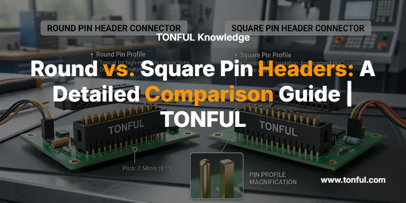
Pin headers are board-mounted electrical connectors consisting of metal pins molded into a plastic housing. They establish removable connections between PCBs, modules, cables, and peripheral devices. The standard pitch for most pin headers is 2.54mm (0.100″), making them compatible with breadboards and prototyping systems.
The fundamental distinction between round and square pin headers lies in their cross-sectional geometry and manufacturing method. Square pins measure 0.64mm (0.025″) per side, while precision round pins typically have a 0.50mm (0.020″) diameter. This dimensional difference directly affects contact area, current capacity, and mating compatibility.

Manufacturing Processes: Stamped vs. Machined
Square Pin Headers: Stamped and Formed
Square pin headers are manufactured through a high-speed stamping process that punches pin shapes from continuous brass strip stock. The metal strip feeds through progressive dies that cut, form, and separate individual pins in a single automated operation. This process produces thousands of pins per hour at minimal material waste.
The stamped manufacturing method makes square pins the most cost-effective connector option available. A complete strip of square pin headers costs less than a single machined round pin header of equivalent length. This dramatic cost advantage makes square pins the default choice for consumer electronics, prototyping, and cost-sensitive applications.
Round Pin Headers: Precision Swiss-Machined
Round pin headers, also called “machine pin headers” or “Swiss machine pins,” are individually lathed from solid metal rod stock using precision CNC turning operations. Each pin is sculpted into a perfectly cylindrical shape with tight dimensional tolerances. This Swiss-machining process, named after the precision lathes historically manufactured in Switzerland, is significantly slower and more material-intensive than stamping.
The precision lathing required for round pins makes them substantially more expensive than stamped alternatives. However, this manufacturing investment delivers superior electrical and mechanical performance characteristics that justify the cost premium in demanding applications.

Electrical Performance Comparison
Contact Resistance and Current Capacity
Contact resistance determines how much electrical opposition exists at the pin-to-socket interface. Lower contact resistance generates less heat during current flow, enabling higher current-carrying capacity before thermal limits are reached.
Round pins provide superior contact performance due to their cylindrical geometry. When a round pin mates with a multi-fingered “tulip” contact socket, the circular cross-section creates uniform contact pressure distributed evenly around the pin’s circumference. This 360-degree contact maximizes the effective contact area and minimizes resistance.
Square pins make contact only at their four corners and edge surfaces when inserted into square sockets. This point-contact geometry creates higher contact resistance compared to the continuous surface contact of round pins. The increased resistance generates more heat under load, limiting current capacity.
Current Rating Specifications
Standard square pin headers typically handle 1A to 3A per pin depending on pin size and plating material. Round machined pins of equivalent dimensions can carry higher currents—often 25-40% more than square pins—due to their lower contact resistance and superior heat dissipation characteristics.
When multiple contacts carry current simultaneously, derating factors apply. A connector with 50% of its contacts energized will carry approximately 75% as much current per contact as the single-contact rating. Engineers must account for this thermal interaction when specifying connectors for power distribution applications.
| Electrical Parameter | Square Pin Headers | Round Pin Headers |
|---|---|---|
| Contact Resistance | Higher (point contact) | Lower (360° contact) |
| Current Rating (typical) | 1A – 3A per pin | 1.5A – 5A per pin |
| Heat Generation | Higher | Lower |
| Power Applications | Signal & low-power | Signal & power-capable |
| Measurement Method | Four-wire milliohmmeter | Four-wire milliohmmeter |

Mechanical Properties and Reliability
Vibration Resistance and Contact Stability
Round pin headers provide superior mechanical stability in vibration-prone environments. The cylindrical geometry and uniform contact pressure create a more secure fit that maintains electrical continuity under mechanical stress. The multi-fingered tulip contacts in round sockets grip the pin circumferentially, preventing loosening from vibration or thermal cycling.
This mechanical advantage makes round pins the preferred choice for automotive terminals and connectors, industrial control systems, aerospace equipment, and any application subject to shock, vibration, or frequent thermal expansion cycles.
Square pins offer adequate mechanical retention for stationary applications but may experience contact degradation in high-vibration environments. The point-contact geometry provides less mechanical grip than the continuous surface contact of round pins.
Insertion and Extraction Forces
Round pins typically require slightly higher insertion forces due to the interference fit between the cylindrical pin and the spring contacts in the socket. However, this tighter fit translates to better contact retention and lower risk of accidental disconnection.
Square pins insert more easily but may exhibit looser fits, particularly after multiple insertion cycles. The stamped edges can also cause wear on socket contacts over time, gradually degrading contact quality.
Durability and Mating Cycles
Machine pin female headers maintain consistent contact performance through thousands of mating cycles. The precision-machined surfaces resist wear and maintain dimensional stability. Round female headers are also cleanly snappable for custom lengths, while standard square female headers require scoring and cleanup, often losing a pin in the process.
| Mechanical Property | Square Pin Headers | Round Pin Headers |
|---|---|---|
| Vibration Resistance | Moderate | Excellent |
| Contact Stability | Good for static use | Superior under stress |
| Insertion Force | Lower | Moderate |
| Mating Cycle Life | 50-100 cycles typical | 500+ cycles |
| Mechanical Retention | Adequate | Superior |
| Best Applications | Prototyping, static | Industrial, automotive |

Critical Compatibility Rule: Round Mates with Round, Square Mates with Square
The most important consideration when selecting pin headers is mating compatibility. Round pins must mate with round sockets, and square pins must mate with square sockets. Mixing geometries creates serious reliability problems.
Inserting a square pin into a round socket designed for machine pins will permanently damage the delicate multi-fingered tulip contacts. The sharp corners of the square pin stretch and deform the precision spring fingers, destroying the socket’s ability to maintain proper contact pressure with round pins.
Conversely, inserting a round pin into a standard square socket creates a loose, unreliable connection. The cylindrical pin cannot make adequate contact with the square socket’s flat contact surfaces, resulting in intermittent connections, high resistance, and potential signal integrity issues.
When specifying pin headers for a design, engineers must ensure that both the male pin headers and mating female header connectors use the same geometry throughout the entire signal chain.
Cost Analysis and Selection Criteria
Price Comparison
Square pin headers represent the most economical connector solution available. Their high-speed stamped manufacturing process, minimal material waste, and widespread availability make them 3-10 times less expensive than equivalent round pin headers.
Round pin headers command a significant price premium due to precision machining requirements, slower production rates, and higher material consumption. However, this upfront cost investment often pays dividends through improved reliability, reduced field failures, and extended service life in demanding applications.
When to Choose Square Pin Headers
Square pin headers are the optimal choice for:
- Prototyping and development work
- Consumer electronics with controlled environments
- Cost-sensitive high-volume production
- Signal-level applications (low current)
- Static installations without vibration
- Breadboard-compatible designs
- Applications using standard SMT vs THT PCB connectors
When to Choose Round Pin Headers
Round pin headers justify their cost premium in:
- Automotive and transportation systems
- Industrial control and automation
- Aerospace and defense equipment
- Medical devices requiring high reliability
- Power distribution applications
- Vibration-prone environments
- Equipment requiring extended service life
- Applications where field failures are costly
When sourcing custom pin headers and PCB connectors from China, working with an experienced terminals and connectors manufacturer like TONFUL ensures you receive guidance on the most appropriate pin geometry for your specific application requirements.
| Selection Factor | Choose Square Pins | Choose Round Pins |
|---|---|---|
| Budget Priority | High cost sensitivity | Performance over cost |
| Operating Environment | Controlled, static | Harsh, vibration-prone |
| Current Requirements | <2A per pin | >2A per pin |
| Reliability Needs | Standard | Mission-critical |
| Production Volume | High-volume consumer | Industrial/automotive |
| Expected Service Life | 2-5 years | 10+ years |
| Field Service Cost | Low replacement cost | High failure cost |

Pitch Variations and Specialized Configurations
While 2.54mm (0.100″) remains the standard pitch for most pin headers, alternative pitches serve specific applications. The female header connector pitch guide covers 1.27mm, 2.00mm, and 2.54mm options in detail.
Finer pitch connectors (1.27mm and 2.00mm) enable higher density connections in space-constrained designs. These smaller pitches are common in embedded systems, IoT devices, and compact consumer electronics. Both round and square pin geometries are available in these alternative pitches, though square pins dominate due to cost considerations.
Box header connectors represent a specialized variant featuring a plastic shroud around the pin array. The shroud provides mechanical protection, polarization keying to prevent incorrect insertion, and compatibility with insulation-displacement connectors (IDC) for ribbon cables. For applications requiring shrouded headers, refer to our pin header vs box header guide.
Surface Finish and Plating Options
Pin header performance is significantly influenced by contact plating material. The most common plating options include tin, gold, and selective gold plating. Each offers distinct advantages for specific operating conditions.
Tin plating provides excellent solderability and cost-effectiveness for general-purpose applications. Gold plating delivers superior corrosion resistance and lower contact resistance for high-reliability applications. Our detailed gold vs tin plating guide for pin and female header connectors examines the performance trade-offs and cost implications of each plating option.
For harsh environments with exposure to moisture, salt spray, or corrosive atmospheres, gold-plated contacts significantly extend service life and maintain stable contact resistance over time.
Frequently Asked Questions
Q: Can I use round pins with square sockets or vice versa?
No. Round pins must mate with round sockets, and square pins must mate with square sockets. Mixing geometries will either permanently damage precision round sockets (when square pins are inserted) or create unreliable connections with high resistance (when round pins are inserted into square sockets).
Q: Are round pin headers always better than square pins?
Not necessarily. Round pins offer superior electrical and mechanical performance but cost significantly more. For prototyping, consumer electronics, and applications without vibration or high current requirements, square pins provide excellent performance at a fraction of the cost. The best choice depends on your specific application requirements and constraints.
Q: What current rating should I use for pin headers?
Standard square pins handle 1-3A per pin, while round pins can carry 1.5-5A per pin. However, you must apply derating factors when multiple pins carry current simultaneously. Consult the connector manufacturer’s specifications and consider ambient temperature, current distribution, and thermal management in your design.
Q: How do I identify whether a pin header is round or square?
Examine the pin cross-section. Square pins have a clearly rectangular profile with visible corners. Round pins appear perfectly cylindrical with no corners. The pin diameter also provides a clue: standard square pins measure 0.64mm (0.025″) per side, while round pins typically measure 0.50mm (0.020″) in diameter.
Q: Can I solder both types to the same PCB?
Yes, both round and square pin headers use standard 2.54mm pitch footprints and can be soldered to the same PCB designs. However, ensure your PCB hole diameter accommodates the pin geometry you select. Round pins often fit in holes sized for square pins, but not always the reverse.
Q: Which type is better for high-vibration automotive applications?
Round pin headers are strongly preferred for automotive and other vibration-prone applications. Their 360-degree contact geometry and superior mechanical retention maintain reliable electrical connections under shock and vibration that would degrade square pin connections.
Conclusion
The choice between round and square pin headers represents a fundamental engineering trade-off between cost and performance. Square pins deliver adequate electrical and mechanical performance for the majority of applications at minimal cost, making them the default choice for consumer electronics, prototyping, and cost-sensitive designs.
Round pin headers justify their price premium in demanding applications where superior contact resistance, higher current capacity, vibration resistance, and extended service life provide tangible value. Industrial equipment, automotive systems, and mission-critical devices benefit from the enhanced reliability that precision-machined round pins deliver.
As a leading manufacturer of electrical PCB connectors and pin header connectors, TONFUL Electric provides both square and round pin header solutions engineered to meet international quality standards. Our technical team assists engineers in selecting the optimal connector geometry, pitch, plating, and configuration for their specific application requirements.
For technical specifications, custom configurations, or assistance with connector selection, contact TONFUL Electric’s engineering support team.
