
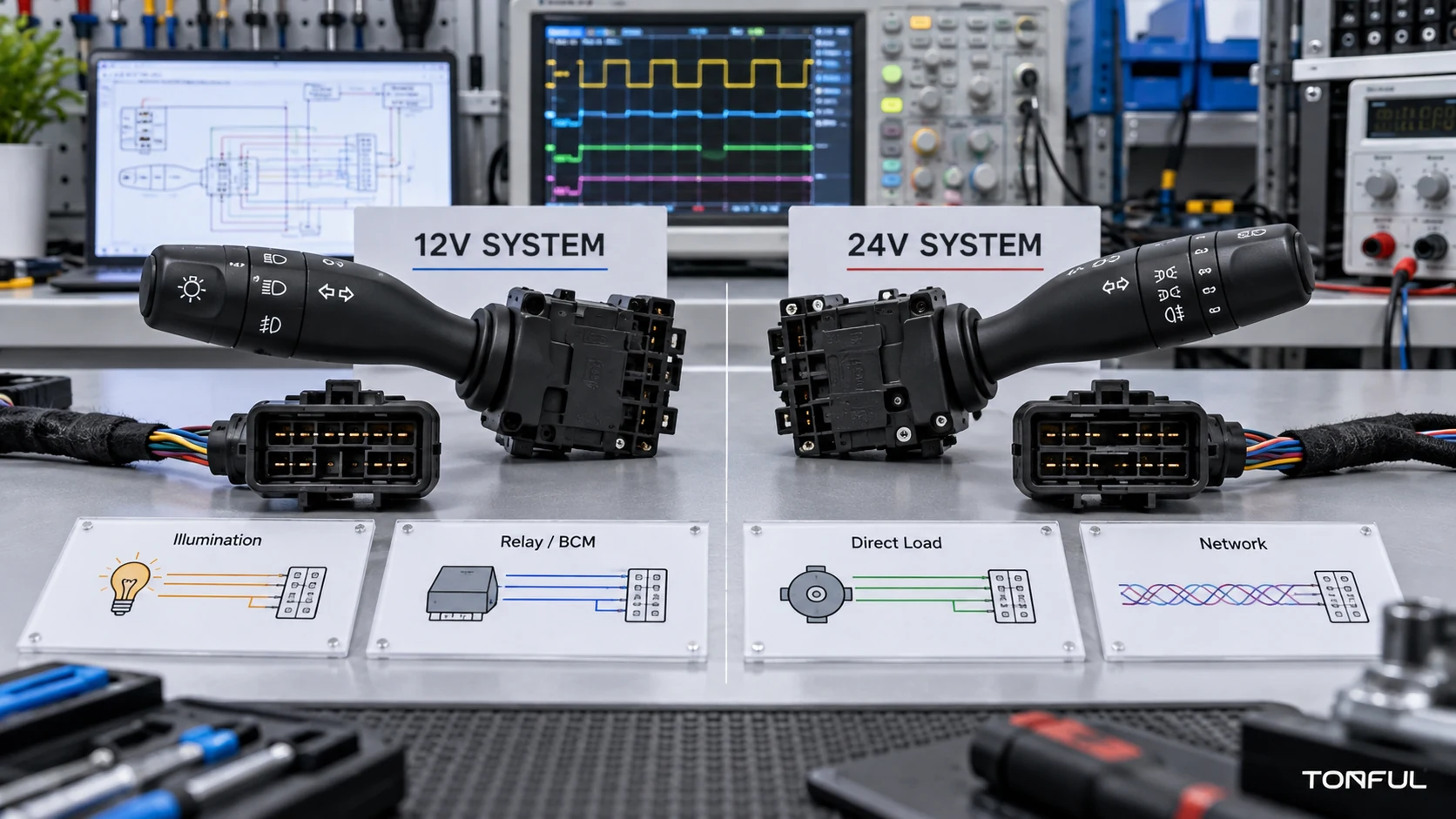
Selecting a 12V vs 24V combination switch requires more than matching nominal voltage, stalk action count and connector shape. A 24V label does not identify the circuit architecture, actual switch load, pinout, stalk position, cab generation, communication method or integrated functions. Two switches can appear interchangeable while using different terminal populations, resistance codes, illumination circuits or module commands.
Start with the exact truck and removed part, then verify fit, electrical behavior, functions, environment and production evidence separately. Voltage ranges, transients, ratings and durability limits must come from controlled project documents.
12V vs 24V Combination Switch Quick Comparison
| Comparison item | 12V system | 24V system | What must be verified |
|---|---|---|---|
| Nominal system voltage | Vehicle 12V electrical system | Vehicle 24V electrical system | Actual operating range, not only the nominal label |
| Same-power load | Usually higher current | Usually lower current | Running, startup, stall and actual load waveform |
| DC interruption | Arcing risk still exists | Higher voltage may increase interruption stress | DC load type, suppression, contact construction and test evidence |
| Relay control | Commonly paired with a 12V coil | Commonly paired with a 24V coil | Coil voltage, current, suppression and control logic |
| Backlight or LED | Requires the applicable 12V design | Requires the applicable 24V design | Polarity, PWM/dimming, brightness and protection |
| Electronic assembly | Must match its specified input range | Requires protection appropriate to the defined 24V environment | Undervoltage, overvoltage, reverse polarity, transients and recovery |
| BCM, LIN or CAN interface | May use a low-voltage signal domain | May also use a low-voltage signal domain | Never infer interface voltage from vehicle nominal voltage |
The table is a screening comparison, not a compatibility declaration. A lower steady current for the same nominal power does not establish that a 24V contact can safely make, carry or interrupt the real DC load.
On this page: Define the Truck Application | Verify Electrical Architecture and Functions | Validate Truck-Duty Performance | Control RFQ, Samples and Production Release
Define the Truck Application
Record More Than Make and Model
Commercial vehicles can retain a model name while changing cab platforms, steering-column harnesses, control modules and switch connectors. Begin with truck manufacturer, model, production date or VIN range, destination market, cab series, trim, stalk position, physical side and LHD/RHD. Record the steering configuration, stalk side, combination-switch functions, electronic options and whether the assembly is passive, coded or networked.
Capture the complete OE service number exactly as printed or published, including prefixes and suffixes. Establish any supersession direction from controlled evidence. A molded housing number may identify a subcomponent rather than the complete switch, while an unverified marketplace number may combine incompatible applications. The combination switch OE-number verification guide provides a structured classification and approval process.

A reliable 24V truck switch selection starts with controlled vehicle, OE, connector, mounting and circuit evidence.
Use a Twelve-Point Application Checklist
| Check field | Evidence required | Release risk if missing |
|---|---|---|
| Vehicle and cab identity | Manufacturer, model, production range, market and cab series | Similar model names may use different steering-column systems |
| Steering and stalk position | Left/right stalk, physical side, mounting orientation and LHD/RHD | Stalk layouts, symbols, harnesses or cancel geometry may differ |
| Complete OE reference | Removed-part label, service catalog and supersession evidence | Base or housing number may identify the wrong assembly |
| Mounting geometry | Bezel, tabs, clips, screw points, depth and trim clearance | A connector match does not guarantee panel fit |
| Connector shell | End-view photograph, keying, latch and dimensions | Similar shells may not mate or lock correctly |
| Populated cavities | Numbered cavity map and terminal population | Empty and populated positions may differ between revisions |
| Electrical architecture | Circuit diagram, diagnostic data or controlled test | Nominal 24V does not identify the load or signal method |
| Function matrix | Every stalk action, direction, detent, lock and illumination state | stalk action count alone misses inactive or optional functions |
| Electronics/software | Hardware, software, coding and communication data | Electronic switch revisions may not be interchangeable |
| Environmental scope | Mounting location, temperature, vibration, dust, liquids and chemicals | Passenger-car assumptions may understate truck service conditions |
| Sample validation | Named samples, procedures, results and acceptance sources | One visual sample cannot prove functional equivalence |
| Supply controls | Approved drawing, packaging, traceability and change notice | Similar variants may be mixed during production or distribution |
The heavy-duty truck combination switch selection guide can be used to compare the removed part and candidate sample in a controlled record.
Verify Electrical Architecture and Functions
Determine What the Switch Actually Carries
A vehicle may use passive contacts, direct lamp or washer-pump switching, relay-coil control, a resistance- or voltage-coded module input, or a networked steering-column controller. The test points and risks differ substantially:
| Architecture | Switch role | Key verification evidence |
|---|---|---|
| Direct-load contacts | Switches a lamp, washer pump or another defined DC load | Pinout, load waveform, contact rating, voltage drop, temperature, suppression and protection |
| Relay-controlled | Commands relay coils while relay contacts carry direct load | Control-side voltage/current, relay logic, output path and fault isolation |
| Resistance-coded | Creates defined resistance windows for stalk action states | Terminal pair, resistance for every state, tolerance, reference circuit and contamination sensitivity |
| Voltage-coded | Produces voltage levels interpreted by a module | Supply/reference, ground, loaded signal voltage, tolerance and diagnostic thresholds |
| Electronic stalk assembly | Processes inputs and may communicate with steering-column/body modules | Power, ground, hardware/software, coding, live data, DTCs and communication |
| LIN/CAN control | Sends digital commands rather than switching the downstream load directly | Network topology, message/state data, termination where applicable, module compatibility and diagnostics |
Do not interchange direct-load and signal-input switches. For a direct-load path, verify running, startup and stall conditions; DC interruption and arcing; contact material; voltage drop and temperature rise; powered endurance; and terminal/connector capacity. Lower steady current at higher voltage does not prove easier contact duty.
A nominal 24V vehicle system does not prove that every switch terminal, illumination circuit, reference input or communication interface operates at 24V. Verify each circuit from the controlled vehicle diagram and product specification. Distinguish vehicle nominal voltage, switch-electronics supply, backlight or indicator supply, downstream load voltage, relay-coil voltage, low-current logic/reference voltage and the power domain serving a LIN/CAN transceiver. Modules or conversion supplies may create other voltage domains.
The combination-switch testing guide explains why circuit architecture, loads and acceptance sources must be identified before continuity, resistance or voltage measurements.
Prevent 12V and 24V Misapplication
| Misapplication | Possible result | Mandatory check |
|---|---|---|
| 12V backlight connected to 24V supply | LED, resistor or PCB overstress | Rated illumination supply, polarity, dimming method and protection |
| 24V backlight used on 12V supply | Low brightness or no illumination | Start voltage, brightness range and PWM compatibility |
| 12V electronic switch used on 24V system | Component damage or loss of protection | Operating range, overvoltage protection and failure behavior |
| 24V module used on 12V system | Undervoltage, resets or communication faults | Undervoltage operation, reset threshold and recovery |
| Contact switch replaced by connector appearance | Wrong output behavior, contact path or load capability | Pinout, continuity matrix, direct-load path and DC load evidence |
| Network switch moved across systems | No communication, wrong commands or DTCs | Protocol, node configuration, hardware and software revisions |
Use a 24V Electrical Verification Matrix
| Verification item | Required evidence |
|---|---|
| Nominal voltage | Separate vehicle and component definitions |
| Operating voltage range | Controlled product or customer specification |
| Cranking/brownout behavior | Required functional state under specified conditions |
| Overvoltage/transient response | Applicable test plan, severity, mode and acceptance result |
| Reverse-polarity behavior | Protection method and defined failure criteria |
| Direct load | Running, startup and stall conditions with duty cycle |
| Contact voltage drop | Specified load, test points, temperature and source limit |
| Illumination | Voltage, polarity, PWM/dimming and brightness requirement |
| Sleep current | Quiescent consumption when electronics are present |
| Network compatibility | Protocol, transceiver domain, node, hardware and software versions |
| Recovery behavior | Function, communication and DTC state after supply disturbance |
ISO 16750-2:2023 describes potential electrical loads for road-vehicle electrical and electronic equipment. It does not prove that a product complies, does not establish one universal 24V truck-switch plan and does not cover EMC. The customer/OEM requirement or approved plan must identify the edition, applicable tests, severity, sequence, operating mode, samples and acceptance criteria.
Build a Complete Function Matrix
Combination switches may integrate turn signals, high/low beam, flash-to-pass, horn, front and rear wipers, intermittent adjustment, washer, cruise, menu controls, illumination and other project-specific actions. Record every neutral position, detent, momentary action, rotary ring, pull or push command, icon, backlight supply and dimming method.
For electronic secondary functions, identify whether command interpretation, coding, diagnostics and fail-safe behavior reside in the stalk assembly, steering-column module, BCM or another controller. Approval of the mechanical switch alone does not validate the completed vehicle-control function.
Validate Truck-Duty Performance
Mechanical, Climatic and Chemical Conditions
Heavy-truck duty cannot be inferred from passenger-car experience. Define and verify:
| Truck-duty condition | Verification focus |
|---|---|
| steering-column mounting | Actual mounting orientation, trim support, sealing and harness routing |
| Temperature | High/low operating and storage states, transitions and functional recovery |
| Steering-column vibration and shock | Mounting integrity, intermittent output, connector retention and physical damage |
| Moisture, dust and cleaners | Exposure method, ingress path, electrical function and material condition |
| Gloved operation | stalk access, force-travel, detent recognition and return |
| UV, symbols and backlight | Color, icon wear, light output and surface degradation |
| Harness and terminals | Wire pull, terminal retention, latch security and fretting evidence |
| Fleet duty | Powered endurance under defined load, rate, dwell and temperature |
| Packaging and storage | Transport vibration, labeling, mixed-part prevention and long-term storage |
ISO 16750-3:2023 addresses mechanical loads, while ISO 16750-4:2023 addresses climatic loads for road-vehicle electrical and electronic equipment. These standards provide a framework, not automatic proof that a particular severity, mounting category or acceptance value applies to the project. The customer/OEM specification or approved qualification plan must define the required tests and limits.
Chemical testing must define the substance, concentration, method, duration, temperature and post-exposure checks. Avoid unsupported “chemical-proof” or “all-weather” claims.
Endurance and Electrical Evidence
Cycle results require load, voltage, rate, dwell, sequence, temperature, samples, monitoring and failure criteria. Separate unloaded mechanical cycling from powered endurance. For direct-current paths, monitor voltage drop, contact resistance under the approved method, temperature, sticking and intermittency. For coded/networked switches, monitor state windows or commands, errors, consumption, illumination and recovery. See the combination switch Endurance Testing guide.
Do not claim that a test “meets truck standard” without naming the standard, edition, clauses, severity, sample count, results and acceptance source. Design qualification, production end-of-line test, periodic audit and field warranty data must remain separate because they answer different questions.
Control RFQ, Samples and Production Release
Send a Complete RFQ Package
| RFQ field | Required project information |
|---|---|
| Application | Vehicle, cab, market, production range, stalk position, LHD/RHD and OE chain |
| Interfaces | Drawings, dimensions, connector, cavity map, pinout and mating component |
| Electrical definition | Architecture, nominal system, operating conditions, loads, protection and diagnostics |
| Functions | Complete stalk action-state, detent, illumination and communication matrix |
| Validation | Applicable standards, customer tests, samples, sequence, limits and reports |
| Quality | Traceability, inspection, test coverage, change control and required approvals |
| Commercial | Annual volume, MOQ, sample/NRE terms, lead time, Incoterm, currency and quotation validity |
| Logistics | Packaging, labels, barcode, destination, service parts and mixed-part prevention |
Commercial values must be confirmed for the actual project; an article should not promise fixed MOQ, capacity, sample time or warranty terms. The combination switch RFQ and Sample Approval Checklist provides a more detailed purchasing record.
Approve Samples by Status

Sample approval must connect the exact truck application, part revision, electrical architecture, test results, packaging and release scope.
| Approval status | Meaning | Purchasing consequence |
|---|---|---|
| Rejected | A mandatory interface, function or evidence requirement failed | No release |
| Conditional | A documented deviation has an owner, risk control and expiry | Limited purchase only within the stated condition |
| Sample approved | Named samples passed the agreed review | Not automatic mass-production approval |
| Production approved | Production-intent evidence and controls were accepted | Purchase only within the approved product, site, process and application scope |
Before production release, confirm drawings, samples, material/contact specifications, tooling traceability, assembly controls, end-of-line coverage, packaging, capacity, contingency and change notification. Use unique labels and scan checks for similar variants.
Final Release Checklist
- Truck, cab, production range, market, stalk position and LHD/RHD are confirmed.
- Complete OE and supersession evidence is retained.
- Mounting, connector, populated cavities and pinout match the approved sample.
- Direct-load, relay, coded or network architecture is verified.
- Every turn, beam, flash, horn, wiper, washer, cruise, illumination and secondary function is tested as applicable.
- Electrical, mechanical and climatic requirements cite controlled sources.
- Test records include samples, equipment, conditions, results, limits and failures.
- Packaging, traceability, production test and change-control requirements are approved.
Work With TONFUL
TONFUL’s automotive combination switch range presents current vehicle applications and OE references. For a 24V truck project, send the complete vehicle and cab information, OE number, stalk position, removed-part and connector photographs, drawings, pinout, architecture, function matrix, required tests, annual forecast and packaging requirements. TONFUL can review the applicable switch and sample scope; final compatibility and release remain tied to controlled project evidence.