
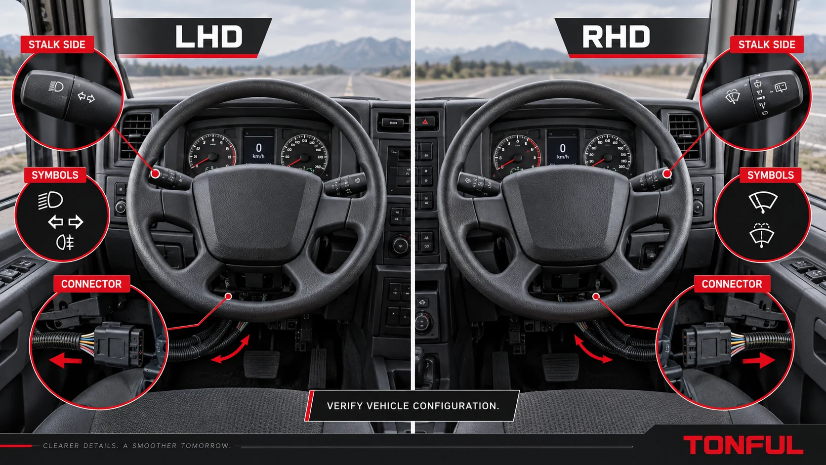
A left-hand-drive vehicle does not automatically use one universal “LHD stalk,” and a right-hand-drive vehicle does not always mirror every steering-column control. Manufacturers may keep turn signals on the same relative side across markets, swap turn and wiper stalks, use a shared housing with different legends, or change the column module and harness. Selecting by steering-wheel position alone can therefore produce a part that mounts but feels wrong, displays inverted symbols or sends incorrect commands.
This guide separates three facts that catalogs often mix together: vehicle steering position, the side of the steering column where the stalk is installed, and the stalk’s actual function. It then shows how to verify geometry, connector, pinout and installed operation without assuming that LHD and RHD versions are interchangeable.
On this page: Define LHD, RHD and Stalk Side | Compare Physical and Electrical Interfaces | Validate Driver Controls | Release Checklist
Define LHD, RHD and Stalk Side
Record Three Separate Fields
| Field | What to record | Common error |
|---|---|---|
| Steering configuration | LHD or RHD based on the driver’s steering-wheel position | Treating market or traffic direction as the only evidence |
| Column installation side | Left-hand stalk, right-hand stalk, upper/lower secondary control | Calling a part “left” from the photographer’s viewpoint |
| Function family | Turn/beam, wiper/washer, cruise/retarder, menu or mixed function | Assuming the left stalk always performs one function worldwide |
Use the seated driver’s viewpoint. Photograph the installed control from the driver’s position and include the steering wheel, column and both stalks. Record destination market, make, model, production or VIN/chassis boundary, cab/trim and option content. A product photo cropped away from the column cannot establish orientation.
Why Manufacturers May Not Mirror the Same Elements
Moving the steering wheel can affect instrument panel, column shroud, ignition or start control, clockspring or steering-angle components, wiring paths and ergonomic reach. However, a manufacturer may retain common steering-column hardware and change only selected parts. Consequently, one LHD/RHD pair may use mirrored housings, another may share the housing but use different stalk legends, and a third may share the complete switch.
Do not convert this variation into a universal rule. Retrieve the vehicle-specific part record and compare the removed switch. The heavy-duty combination-switch selection guide provides the broader vehicle/OE/function sequence.
Use the Complete OE Chain
Capture every character, suffix and revision from the removed part. Identify whether each number is an OE service, superseded OE, supplier, engineering, casting or customer-stock number. Record replacement direction and any LHD/RHD, market or production restriction. A shared molded housing number may appear on both versions even when the complete assembly differs.
TONFUL’s OE-number cross-reference guide shows how to keep number type and validation status visible. An unresolved left/right description is not a pass.
Compare Physical and Electrical Interfaces
Mounting, Reach and Movement
Compare housing handedness, column-shroud contour, locating tabs, fasteners, connector position, stalk angle, lever length, driver reach, travel, detents, momentary return, rotary direction, trim clearance and harness strain. A mirrored lever can have a different internal actuator direction or self-cancel interface even if the housing seems symmetric.
For turn-signal controls, compare the cancel cam/ring relationship, pawl engagement side and lever return behavior using the approved column interface. Never force the lever through the cancel mechanism. The turn-signal self-cancel guide explains the mechanism and evidence boundaries.

Record steering configuration, column side and function separately; the layout shown is conceptual and not a universal vehicle arrangement.
Symbols and Driver Interpretation
Check every symbol, text label, reading direction, illumination zone and rotary OFF position. A switch can be electrically equivalent yet unsuitable if symbols are upside down, hidden or assigned to a different function. UN Regulation No. 121 addresses vehicle-level location and identification of controls, tell-tales and indicators and includes requirements for control identification to be perceptually upright in its applicable scope. See the UNECE Regulation No. 121 document page.
That regulation does not certify an individual replacement stalk, determine LHD/RHD interchangeability or supply a pinout. Confirm the applicable market and vehicle approval requirements with the customer or responsible authority.
Connector, Harness and Pinout
Photograph removed and candidate connector faces straight-on with latch/keyway in the same orientation. Compare shell family, polarization, cavity count, populated terminals, blanks, terminal type, seal and latch. Then compare connector position and harness exit in the installed column; a connector facing the wrong direction can create strain even if it mates.
Build a cavity/state table from the controlled diagram. LHD/RHD versions may use the same shell with different wire routing or pin allocation, or may be electrically identical. Neither outcome should be assumed. The pinout and connector guide provides a reusable viewing-direction method.
Electrical Architecture
Identify each function as direct contact/load, relay request, resistance/voltage-coded input, LIN/CAN or local module output. A market variant can change an electronic revision or software configuration without changing the connector. For networked assemblies, compare hardware and software revision, node role, coding, wake/sleep and DTC behavior.
Never apply battery voltage or a test lamp to an unidentified terminal. The analog, resistive, LIN and CAN stalk guide explains architecture-specific testing.
Validate Driver Controls
Use a Copyable LHD/RHD Record
| Verification field | Removed part | Candidate sample | Evidence source | Result |
|---|---|---|---|---|
| Vehicle, market and VIN/chassis scope | Enter | Enter | Vehicle record | Pass/Fail |
| Steering configuration | LHD/RHD | LHD/RHD | Installed vehicle | Pass/Fail |
| Column side and driver-view photo | Enter | Enter | Oriented photo | Pass/Fail |
| Complete OE number/revision | Enter | Enter | Label/catalog | Pass/Fail |
| Function set and symbols | Enter | Enter | Approved matrix | Pass/Fail |
| Mounting geometry and stalk clearance | Enter | Enter | Drawing/installed sample | Pass/Fail |
| Cancel interface or rotary direction | Enter | Enter | Mechanism/function test | Pass/Fail |
| Connector orientation/cavities | Enter | Enter | End-view map | Pass/Fail |
| Electrical architecture and states | Enter | Enter | Diagram/test | Pass/Fail |
| Coding/initialization/DTC status | Enter | Enter | Vehicle procedure | Pass/Fail |
| Driver operation and final disposition | Reference | Sample/lot | Approval record | Approved/Conditional/Rejected |
Test every maintained and momentary action: turn, beam, flash, horn, wiper, washer, intermittent adjustment, cruise, retarder, menu and secondary controls only as fitted. Observe instrument or module recognition and downstream operation separately. A lever can produce the correct local contact while a controller, wiring or actuator fault prevents the vehicle function.
Diagnose Typical Mismatch Symptoms
| Symptom | Likely direction | Next evidence |
|---|---|---|
| Stalk mounts on the wrong side or symbols face away | Wrong handed housing/market variant | Driver-view photo, part revision and mounting drawing |
| Lever contacts column trim | Stalk angle, housing depth or shroud mismatch | Controlled dimensions and installed clearance |
| Turn lever does not cancel | Cancel geometry or orientation mismatch | Cam/pawl interface and return test |
| Rotary markings operate in reverse order | Mirrored mechanics or wrong coded-state mapping | Mechanical direction and raw state table |
| Connector mates but functions are swapped | Different pinout or internal coding | Cavity/function matrix |
| Harness is tight at full column adjustment | Connector/harness exit mismatch | Routing and strain through adjustment range |
| Symbols are not upright or illumination differs | Wrong market/side legend or illumination circuit | Driver-view appearance requirement |
| New electronic switch creates DTCs | Hardware/software/coding mismatch | Revision, network and configuration evidence |

Installed validation should cover driver reach, symbol orientation, column clearance, harness routing and every required command.
Release Checklist
Approve only when vehicle and market, VIN/chassis boundary, steering configuration, column side, complete OE chain, symbols, geometry, cancel interface, connector, pinout, architecture, every function and installed diagnostic state agree with controlled requirements. Retain the oriented photographs so “left” and “right” cannot be reinterpreted later.
Sample approval applies only to the named configuration. Control changes to housing handedness, stalk body, symbols, illumination, connector, contacts, coded electronics, PCB, software, tooling and manufacturing site. Use Conditional only for a bounded deviation with closure evidence.
Packaging and labeling must preserve the same distinction. Put the complete approved number and revision, LHD/RHD scope where controlled, stalk side from the seated-driver viewpoint, market or project identifier, lot and quantity on the product or unit pack as required by the drawing. Do not label a carton only “left switch” or “RHD type.” At receiving inspection, compare an oriented reference photo, label, mounting features, connector face, symbols and basic function identity before mixing stock locations.
For fleets or distributors carrying both variants, use separate bin codes and barcode validation. A picking control should reject an LHD/RHD or left/right mismatch before shipment. If returned material has been removed from its original pack, quarantine it until the label, connector, function and orientation are re-established; appearance alone is not sufficient for restocking.
Work With TONFUL
Packaging and warehouse labels should state the approved steering configuration and stalk position independently. This prevents a physically similar RHD variant from entering an LHD bin after receiving inspection, relabeling or a marketplace return.
TONFUL’s automotive combination switch range presents current application references. Send the exact vehicle/market, VIN or chassis boundary, LHD/RHD, seated-driver photo, stalk side, complete OE label, connector end view, required functions and sample plan. TONFUL can compare the request with controlled product evidence; steering position or a visually mirrored housing alone is not treated as compatibility proof.