
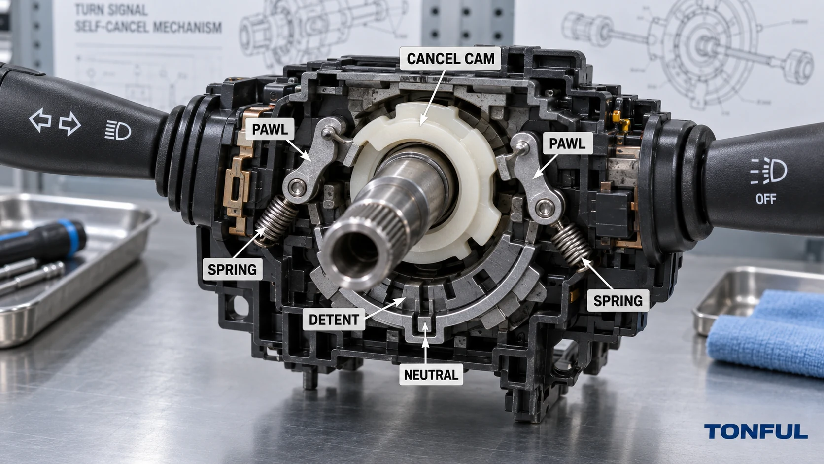
A mechanical turn-signal self-cancel system returns the stalk from a latched left or right position to neutral as the steering wheel comes back after a turn. It normally relies on an interaction between a rotating steering-column cancel cam and spring-loaded parts inside the turn-signal switch. A failed cancel function is therefore not automatically proof that the electrical contacts are defective: the cause may be the switch mechanism, the steering-column cam, installation position, missing engagement, housing damage or an electronic control strategy.
This guide explains the common mechanical sequence, the evidence needed to diagnose a complaint and the limits of replacement claims. Designs vary by vehicle. Use the vehicle-specific service information, drawing and approved sample; do not treat the conceptual diagrams below as an acceptance standard.
On this page: Mechanism | Failure Modes | Diagnosis | Validation
How the Mechanical Cancel Sequence Works

Conceptual sequence only. The actual cam direction, pawl shape, steering angle and engagement geometry are vehicle-specific.
Main Parts and Their Roles
| Part or interface | Typical role | Evidence to verify |
|---|---|---|
| Stalk and carrier | Transfers the driver’s movement into the left, neutral or right mechanism position | Travel, free play, latch and return behavior |
| Detent cam or track | Holds the selected turn position and defines the release path | Surface condition, profile, wear and assembly orientation |
| Spring and plunger | Applies centering or detent force | Presence, seating, force evidence and deformation |
| Cancel pawl or finger | Moves into the path of the rotating cancel feature when a turn is selected | Extension, pivot freedom, spring bias and wear |
| Steering-column cancel cam | Rotates with the specified steering component and contacts the pawl | Correct part, orientation, height, runout and engagement |
| Housing and mounting datums | Keep the switch concentric and angularly aligned to the steering shaft | Fastening, locating tabs, damage and installed position |
| Electrical contact or sensor | Changes the turn-signal output or request state | Left/neutral/right truth table and module recognition |
The stalk first moves the carrier into a detent that holds a left or right indication. That movement also positions a cancel pawl or comparable element where the steering-column cam can interact with it. During steering movement in the turn direction, many mechanisms allow the cam to pass or deflect the pawl without cancelling. When the wheel returns in the cancelling direction, the cam drives the pawl through the release path, overcomes the detent and allows the spring-loaded carrier and stalk to return to neutral.
The exact arrangement differs. Published turn-signal mechanism patents illustrate common engineering principles such as a bracket, detent, ratchet or pawl, elastic member and steering-shaft cancel cam. For example, US4503296A describes a steering-column mechanism that returns the switch during steering-wheel rotation in the cancelling direction. A patent explains one design, not a universal service procedure or proof that a TONFUL product uses that construction.
Anti-Cancel Travel Is Intentional
The mechanism must usually tolerate steering movement farther into the selected turn without immediately returning the stalk. A pawl may deflect, pivot or ride past the cam in this anti-cancelling direction, then re-enter its ready position. Cancellation occurs when the cam approaches from the return direction. If the pawl binds, the spring is weak or the cam/pawl geometry is wrong, the system can cancel too early, fail to cancel, click repeatedly or jam.
Small lane-change movements may not cross the designed engagement angle. That behavior should not be called a defect until the vehicle procedure defines the required steering movement. Likewise, a lane-change momentary function may be electronic and may not use the mechanical latch at all.
Why Self-Cancel Mechanisms Fail
Failure-to-Evidence Matrix
| Symptom | Evidence to collect | Likely investigation path | Immediate control |
|---|---|---|---|
| Neither direction cancels | Installed alignment, cam presence, engagement video and switch latch | Missing/wrong cam, excessive gap, switch not seated or common mechanism damage | Confirm manual return; quarantine affected configuration |
| Only left or right fails | Direction-specific pawl, track, wear, spring and cam contact marks | One-sided wear, broken feature, asymmetric alignment or housing damage | Record direction and steering sequence before disassembly |
| Cancels too early | Steering angle, pawl extension, detent force and mounting angle | Wrong geometry, incorrect part, weak detent or misalignment | Stop universal fitment claim |
| Cancels too late or not after a full turn | Cam travel, gap, pawl motion, free play and column interface | Insufficient engagement, bent/missing feature or wrong switch variant | Verify exact OE/application chain |
| Cancels while steering farther into the turn | Direction of cam contact and pawl compliance | Pawl cannot deflect in anti-cancel direction, assembly error or interference | Preserve mechanism position and marks |
| Stalk will not latch | Force/travel trace, detent parts, spring and housing | Broken detent, contamination, wear, incorrect assembly or fixture side load | Do not continue cycling and erase evidence |
| Stalk remains mechanically neutral but signal stays on | Electrical truth table, BCM data, wiring and relay/output state | Contact, coded signal, module or harness issue rather than cancel mechanics | Diagnose electrical path separately |
| Clicking, grinding or intermittent return | Video/audio, contact marks, debris, lubrication and housing distortion | Pawl/cam interference, wear particles, dry or wrong lubricant, cracked support | Inspect before further operation |
Wear is only one cause. Incorrect steering-wheel or clockspring work, a missing cancel feature, wrong steering-column component, an incompletely seated switch, over-tightened or distorted housing, foreign material and unapproved lubrication can create the same complaint. A visually identical replacement may also have different cancel-pawl height, mounting offset or internal release geometry.

Compare engagement, interference and directional wear evidence before assigning the failure to the switch mechanism.
A recent NHTSA recall document provides a real field example: the 2024 recall repair information describes an interference condition in a steering-column control module turn-signal mechanism that can disable self-cancelling. That document applies only to the identified recall population; it should not be generalized into a diagnosis or acceptance limit for unrelated vehicles.
Diagnose the Complaint in a Controlled Order
1. Confirm the Complaint and Safety Boundary
Record whether the stalk latches, whether the lamps or module request activate correctly, which direction fails, the steering movement used and whether manual return works. Do not rotate an exposed steering shaft or disturb an airbag/clockspring assembly without the vehicle procedure and qualified personnel. Steering-column service can involve supplemental-restraint precautions beyond the switch itself.
2. Verify Vehicle and Part Identity
Capture the VIN or chassis context, market, production date, LHD/RHD, complete OE number, supersession evidence, mounting side, connector and function set. The combination-switch OE cross-reference guide explains why housing numbers and marketplace interchange lists are insufficient.
3. Separate Electrical Operation From Mechanical Cancellation
With the approved method, verify left, neutral and right electrical states before judging the cancel mechanism. A stalk can return mechanically while a contact, resistor-coded state, module input or output remains active. Conversely, the electrical command can be correct while the stalk fails to return. Use the pinout and connector-layout guide to control viewing direction and the state truth table.
4. Inspect the Installed Interface
Check mounting datums, fasteners, gaps, concentricity, connector/harness strain and visible cancel-cam engagement. Compare the removed part and candidate at the pawl location, housing depth and steering-column interface rather than only the stalk shape. Look for one-sided witness marks showing contact, no-contact or excessive interference.
5. Observe the Cancel Sequence
Operate the mechanism only as the vehicle or fixture procedure permits. Record neutral, selected direction, anti-cancel steering movement, return movement, cam contact and neutral release. Use consistent viewing direction and slow-motion video when useful. Never force the stalk to obtain a passing result.
6. Measure Mechanical Degradation
When the plan requires it, record stalk force/travel, detent retention, return force, free play and repeatability with identified equipment. Compare initial, complaint and post-investigation results with the project-specific requirement. The mechanical endurance testing guide explains fixture alignment, first-failure preservation and invalid-test handling.
Validate a Replacement and Control the Evidence
Replacement Approval Checklist
| Verification item | Required record | Release condition |
|---|---|---|
| Application identity | Vehicle, production range, market, steering configuration and OE chain | Exact scope resolved |
| Mounting and cam interface | Datums, installed depth, angular position, gap and contact path | Matches controlled requirement |
| Left/right latch | Force/travel and repeatable detent behavior | Both directions meet source criteria |
| Anti-cancel passage | Controlled movement in the selected-turn direction | No unintended release or jam |
| Cancel return | Defined return movement for both directions | Neutral return meets vehicle/project procedure |
| Electrical state | Left/neutral/right truth table and module/output evidence | Correct state follows mechanism |
| Secondary functions | Beam, horn, wiper, washer, cruise or menu as applicable | No collateral loss |
| Installed validation | Named sample, vehicle, conditions, approver and date | Approved only within tested scope |
Do not publish a universal steering angle or cancellation threshold. Vehicle geometry, steering ratio, cam design and service procedure determine the applicable movement. A bench fixture should reproduce mounting and engagement without imposing side load, but an approved bench result does not replace final installed validation when the project requires it.
Maintain photographs, video, force/travel data, sample identity, lot, test conditions, first-failure evidence and the acceptance-source document. If disassembly is authorized, preserve component orientation and wear particles. Do not repeatedly operate a failed mechanism until contact marks and the first-failure position are lost.
The TONFUL combination-switch product page presents current application references. Send the exact vehicle, OE number, steering configuration, removed-part photographs, connector view, cancel-interface images, symptom sequence and approval requirements. Final release remains tied to controlled evidence and an approved sample.
Work With TONFUL
TONFUL can review an identified combination-switch application, sample and self-cancel evidence package. Provide the vehicle scope, complete OE reference, steering configuration, connector, mounting interface, left/right symptom, photographs and validation plan. Product compatibility and cancel performance must be confirmed for the named project rather than inferred from stalk appearance.