Surface mount device (SMD) pin headers have become the backbone of modern PCB design, enabling faster assembly, higher component density, and improved reliability in electronic products. As circuit boards shrink and production volumes increase, understanding how to properly select and implement SMD pin headers is critical for electrical engineers and PCB designers. This comprehensive guide covers everything from basic specifications to advanced design considerations, helping you make informed decisions for your next project.
What Are SMD Pin Headers?
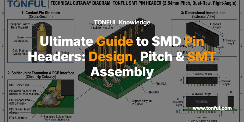
SMD pin headers, also known as surface mount technology (SMT) pin headers, are electrical connectors designed to mount directly onto the surface of a printed circuit board without requiring through-holes. Unlike traditional through-hole technology (THT) pin headers where pins pass through drilled holes, SMD variants feature pins bent at 90-degree angles that solder directly to surface pads.
These connectors serve as the interface between PCBs, enabling board-to-board connections, signal transmission, and modular system architectures. The transition from THT to SMD mounting represents a fundamental shift in electronics manufacturing, driven by the need for automation, miniaturization, and cost efficiency. For engineers evaluating pin header connectors for their designs, understanding the SMD variant’s unique characteristics is essential.

Key Advantages of SMD Pin Headers
The adoption of SMD pin headers in modern electronics stems from several compelling advantages that directly impact manufacturing efficiency and product performance.
Automated Assembly Compatibility
SMD pin headers are specifically engineered for automated pick-and-place equipment, enabling high-speed, high-precision assembly that dramatically reduces labor costs and human error. Modern SMT lines can place thousands of components per hour with positional accuracy within ±0.05mm, making them ideal for mass production scenarios.
Space Optimization
By eliminating the need for through-holes, SMD pin headers free up valuable PCB real estate. This allows for double-sided component placement and enables ultra-compact footprints with pitch options as small as 1.0mm or 1.27mm for space-constrained applications. The reduced board thickness requirements also contribute to lighter, more portable end products.
Enhanced Signal Integrity
Shorter electrical paths between components minimize parasitic inductance and capacitance, improving signal integrity—particularly critical for high-speed digital interfaces and RF applications. When paired with proper PCB connector design practices, SMD headers can support data rates exceeding several Gbps.
Cost Efficiency at Scale
While individual SMD components may cost slightly more than THT equivalents, the total cost of ownership favors SMD in medium to high-volume production. Elimination of drilling operations, faster assembly times, and reduced material handling translate to significant per-unit savings once production volumes exceed several thousand units.
SMD Pin Header Specifications and Types
Selecting the appropriate SMD pin header requires understanding the key specifications that define performance, compatibility, and reliability.
| Specification | Common Values | Design Impact |
|---|---|---|
| Pitch | 1.0mm, 1.27mm, 2.0mm, 2.54mm | Determines pin density and PCB space requirements |
| Pin Count | Single row: 2-50 pins Dual row: 4-100 pins |
Affects connector size and current capacity |
| Current Rating | 1A – 3A per contact | Limits power delivery capability |
| Operating Temperature | -40°C to +105°C (standard) -55°C to +125°C (extended) |
Defines environmental suitability |
| Insulator Material | PBT (through-hole compatible) PA6T/LCP (reflow compatible) |
Determines thermal resistance during soldering |
| Contact Plating | Tin, Gold (flash or selective) | Impacts corrosion resistance and contact reliability |
| Mounting Orientation | Vertical (straight), Right-angle (90°) | Determines mating direction and board layout |
Pitch Selection Considerations
The pitch—or center-to-center spacing between adjacent pins—is perhaps the most critical specification. Standard 2.54mm (0.1″) pitch remains popular for compatibility with legacy systems and prototyping boards, while 2.0mm pitch offers a balance between density and manufacturability. For ultra-compact designs, 1.27mm and 1.0mm pitch variants enable maximum component density but demand tighter manufacturing tolerances and more sophisticated assembly equipment.
When comparing round vs square pin headers, consider that square pins typically provide better mechanical stability and higher current capacity due to increased contact area.

Critical Design Considerations
Successful SMD pin header implementation requires attention to several design factors that directly impact manufacturing yield and long-term reliability.
PCB Footprint Design
The single most important rule is to strictly adhere to the manufacturer’s recommended PCB footprint. These layouts are developed based on IPC-7351 standards to ensure optimal solder fillet formation at three critical areas: the toe, heel, and sides of each pin. Deviating from recommended pad dimensions can lead to tombstoning, insufficient solder joints, or bridging during reflow.
Thermal Management and Current Capacity
While SMD pin headers offer numerous advantages, their current-carrying capacity requires careful evaluation. Contact temperature rise is governed by bulk resistance, current level, and heat dissipation to surrounding materials. Industry standards typically specify a 30°C temperature rise above ambient as the maximum safe operating point, with a 20% derating factor applied for reliability margins.
For power applications, consider these thermal design guidelines:
- Single contact derating: Apply 50-60% derating from maximum rated current for long-term reliability
- Multiple powered contacts: When several adjacent pins carry current simultaneously, heat accumulation requires additional derating of 20-30%
- PCB thermal management: Use copper pours and thermal vias near high-current contacts to improve heat dissipation
- Wire gauge matching: Ensure connected wire gauge supports the intended current without creating a thermal bottleneck
The table below compares typical current ratings across common SMD pin header configurations:
| Pin Pitch | Single Contact Rating | Dual Row (All Pins Powered) | Recommended Operating Current |
|---|---|---|---|
| 1.0mm | 1.0A | 0.6A per pin | 0.5A per pin |
| 1.27mm | 1.5A | 0.9A per pin | 0.75A per pin |
| 2.0mm | 2.0A | 1.2A per pin | 1.0A per pin |
| 2.54mm | 3.0A | 1.8A per pin | 1.5A per pin |
When designing custom wire harness assemblies that interface with SMD pin headers, ensure wire gauge selection matches the connector’s current capacity.
Mechanical Strength Limitations
The primary weakness of SMD pin headers compared to through-hole variants is mechanical strength. SMD contacts rely solely on surface solder joints for retention, lacking the mechanical anchoring that through-hole pins provide. This makes them vulnerable to mechanical stress from cable pulls, connector insertions, and thermal cycling.
Mitigation strategies include:
- Mechanical anchoring features: Select SMD headers with plastic pegs or metal mounting tabs that provide additional mechanical support
- Strain relief: Implement cable strain relief mechanisms to prevent force transmission to the connector
- Conformal coating: Apply conformal coating around solder joints to improve mechanical durability
- Adhesive reinforcement: Use epoxy or UV-curable adhesive to bond the connector body to the PCB
- Design for mating cycles: For applications requiring frequent connect/disconnect cycles, consider box header connectors or shrouded variants that guide mating and reduce insertion force

Reflow Soldering Considerations
SMD pin headers must survive the reflow soldering process, which subjects components to precisely controlled thermal profiles defined by J-STD-020 standards. For lead-free soldering, peak temperatures typically reach 260-265°C for 5-10 seconds.
Material Selection for Reflow Compatibility
Not all pin header materials can withstand reflow temperatures. The insulator material determines thermal resistance:
- PBT (Polybutylene Terephthalate): Suitable for wave soldering and hand soldering up to 200°C, but NOT recommended for reflow processes
- PA6T (Polyamide 6T): Reflow-compatible, withstands 230°C for 30-60 seconds and peak temperatures of 260°C for 5-10 seconds
- LCP (Liquid Crystal Polymer): Premium material offering superior dimensional stability and thermal resistance up to 280°C
Always verify the connector’s temperature rating before selecting it for lead-free reflow processes. Using a connector not rated for high-temperature soldering can result in plastic deformation, warping, or complete failure.
Preventing Common Reflow Defects
Several defects can occur during reflow soldering of SMD pin headers:
| Defect | Cause | Prevention |
|---|---|---|
| Tombstoning | Uneven heating or pad size mismatch causing component to stand on end | Balance pad sizes, ensure symmetric thermal mass, use proper stencil thickness |
| Solder Bridging | Excessive solder paste or misalignment | Optimize stencil aperture design, maintain proper paste volume, ensure accurate placement |
| Insufficient Solder | Inadequate paste volume or poor wetting | Verify stencil thickness (typically 0.125mm), ensure proper reflow profile, check pad surface finish |
| Component Skewing | Uneven solder surface tension during reflow | Add alignment pegs, use pick-up caps for placement accuracy, optimize pad geometry |
| Voiding | Trapped flux gases or moisture | Use proper paste storage, implement adequate preheat phase, consider vacuum reflow for critical applications |
For engineers working with female header connectors as mating counterparts, ensure both halves use compatible plating materials to prevent galvanic corrosion.

Contact Plating Options and Selection
The choice between gold vs tin plating significantly impacts connector performance, cost, and application suitability.
Tin Plating
Tin plating is the most economical option, offering good solderability and adequate corrosion resistance for most applications. However, tin is susceptible to whisker growth—a phenomenon where conductive tin filaments spontaneously grow from the surface, potentially causing short circuits. Modern matte tin plating processes with controlled grain structure minimize this risk.
Best for: Cost-sensitive applications, high-volume consumer electronics, environments with controlled humidity
Gold Plating
Gold plating provides superior corrosion resistance, stable contact resistance over time, and excellent durability for high mating-cycle applications. Two variants exist:
- Gold flash (0.05-0.13 μm): Thin gold layer over nickel underplate, suitable for low-insertion applications
- Selective gold (0.76-1.27 μm): Thicker gold on contact areas only, balancing cost and performance
Best for: High-reliability applications, harsh environments, frequent mating cycles, long product lifecycles
When sourcing custom pin headers from China, clearly specify plating requirements and request certification of plating thickness to ensure quality compliance.
Pitch Selection Guide
Choosing the appropriate pitch involves balancing several competing factors:
| Pitch | Advantages | Disadvantages | Typical Applications |
|---|---|---|---|
| 2.54mm (0.1″) | Industry standard, breadboard compatible, easier hand soldering, lower cost | Larger footprint, lower density | Prototyping, legacy system interfaces, Arduino/Raspberry Pi shields |
| 2.0mm | Good density/manufacturability balance, widely available | Less common than 2.54mm in hobby market | Industrial controls, telecommunications equipment, test fixtures |
| 1.27mm (0.05″) | High density, compact designs, good signal integrity | Requires precision assembly, higher cost | Embedded systems, IoT devices, portable electronics |
| 1.0mm | Maximum density, ultra-compact | Difficult to rework, specialized assembly required, limited availability | Smartphones, wearables, miniaturized medical devices |
For detailed guidance on pitch selection for female headers, consult our comprehensive female header connector pitch guide.

Design Best Practices
Implementing these proven practices will improve manufacturing yield, reliability, and long-term performance:
Layout and Routing
- Maintain symmetry: Design pad layouts with thermal symmetry to prevent uneven heating during reflow
- Provide test access: Include test points near critical signal pins for in-circuit testing and debugging
- Consider rework: Leave adequate clearance around SMD headers for hot air rework tools
- Ground plane management: Use thermal relief connections for ground pins to prevent excessive heat sinking during soldering
Assembly Considerations
- Pick-up cap specification: Order SMD headers with removable pick-up caps for automated placement, removing caps post-reflow
- Orientation marking: Add clear silkscreen indicators for pin 1 and connector orientation
- Stencil design: Use 1:1 stencil aperture ratio for standard pitches; reduce to 0.9:1 for fine-pitch applications to prevent bridging
- Reflow profile validation: Validate thermal profiles using thermocouples attached to actual connectors on representative PCBs
System-Level Design
- Mating connector selection: Ensure female header connectors or wafer connectors have compatible pitch, pin count, and plating
- Keying and polarization: Implement mechanical keying to prevent reverse insertion, especially for power connections
- Cable assembly integration: When designing custom data cable assemblies, consider the mechanical interface and strain relief requirements
- Future-proofing: Design footprints that can accommodate both SMD and THT variants when possible for manufacturing flexibility
SMD vs. Through-Hole: Making the Right Choice
While SMD pin headers offer numerous advantages, through-hole technology remains relevant for specific applications. Understanding when to use each approach is critical for optimal design outcomes.
Choose SMD pin headers when:
- Production volumes exceed 1,000 units
- Board space is constrained
- Automated assembly is available
- Double-sided component placement is required
- High-speed signal integrity is critical
Choose through-hole pin headers when:
- Mechanical strength is paramount
- Frequent connect/disconnect cycles are expected
- Hand assembly or field repair is necessary
- Prototyping or low-volume production
- Extreme environmental conditions require maximum reliability
For a detailed analysis, refer to our article comparing pin header vs box header configurations.
Quality Assurance and Testing
Ensuring SMD pin header reliability requires comprehensive testing throughout the design and manufacturing process:
- Visual inspection: Automated optical inspection (AOI) verifies placement accuracy and solder joint quality
- X-ray inspection: For critical applications, X-ray imaging reveals hidden defects like voiding or insufficient solder penetration
- Pull testing: Mechanical pull tests validate solder joint strength, typically requiring 5-10N retention force per pin
- Electrical testing: In-circuit testing (ICT) or flying probe testing verifies electrical continuity and isolation
- Environmental testing: Salt spray (ASTM B117), thermal cycling, and humidity testing validate long-term reliability
When working with terminals and connectors manufacturers, request qualification test reports demonstrating compliance with relevant industry standards.
Frequently Asked Questions
Q: Can SMD pin headers be hand-soldered?
A: Yes, but it requires skill and proper tools. Use a fine-tip soldering iron (0.5-1mm tip), quality flux, and work quickly to avoid heat damage to the plastic insulator. However, hand soldering defeats many advantages of SMD technology and is generally not recommended for production.
Q: What’s the maximum current rating for SMD pin headers?
A: Current ratings vary by pitch and design, typically ranging from 1A (1.0mm pitch) to 3A (2.54mm pitch) per contact. Always apply 50-60% derating for reliability, and reduce further when multiple adjacent pins carry current simultaneously due to heat accumulation.
Q: How do I prevent SMD pin headers from falling off during reflow?
A: Ensure proper solder paste volume, use headers with alignment pegs or pick-up caps, verify pad design matches manufacturer recommendations, and optimize your reflow profile for the specific connector material. Some manufacturers offer SMD headers with adhesive backing for additional retention.
Q: Are SMD pin headers compatible with standard 0.1″ breadboards?
A: Standard 2.54mm pitch SMD headers match breadboard spacing, but the surface-mount pins won’t insert into breadboard holes. For prototyping, use through-hole variants or solder wires to the SMD header for breadboard connection.
Q: What’s the difference between SMD and SMT pin headers?
A: These terms are often used interchangeably. SMD (Surface Mount Device) refers to the component itself, while SMT (Surface Mount Technology) refers to the assembly process. Both describe the same type of connector designed for surface mounting.
Q: Can I mix different plating types on mating connectors?
A: While possible, mixing gold and tin plating can lead to accelerated wear and fretting corrosion. For best results, use matching plating on both male and female connectors, or use gold on the higher-cycle connector mating with tin on the lower-cycle side.
Conclusion
SMD pin headers represent a critical enabling technology for modern electronics manufacturing, offering unmatched advantages in automation, density, and cost efficiency. Success requires careful attention to specification selection, PCB footprint design, thermal management, and reflow soldering parameters. By following the guidelines outlined in this guide and partnering with experienced electrical PCB connector manufacturers like TONFUL Electric, designers can confidently implement SMD pin headers that deliver reliable performance across demanding applications.
Whether you’re designing IoT devices, industrial controls, or consumer electronics, understanding the nuances of SMD pin header technology will help you create products that are manufacturable, reliable, and cost-effective. As electronics continue to shrink and production volumes increase, mastery of surface mount interconnect technology becomes increasingly essential for competitive product development.
For custom SMD pin header solutions tailored to your specific application requirements, contact TONFUL Electric’s engineering team to discuss your project needs and receive expert guidance on connector selection, PCB layout optimization, and manufacturing support.
