
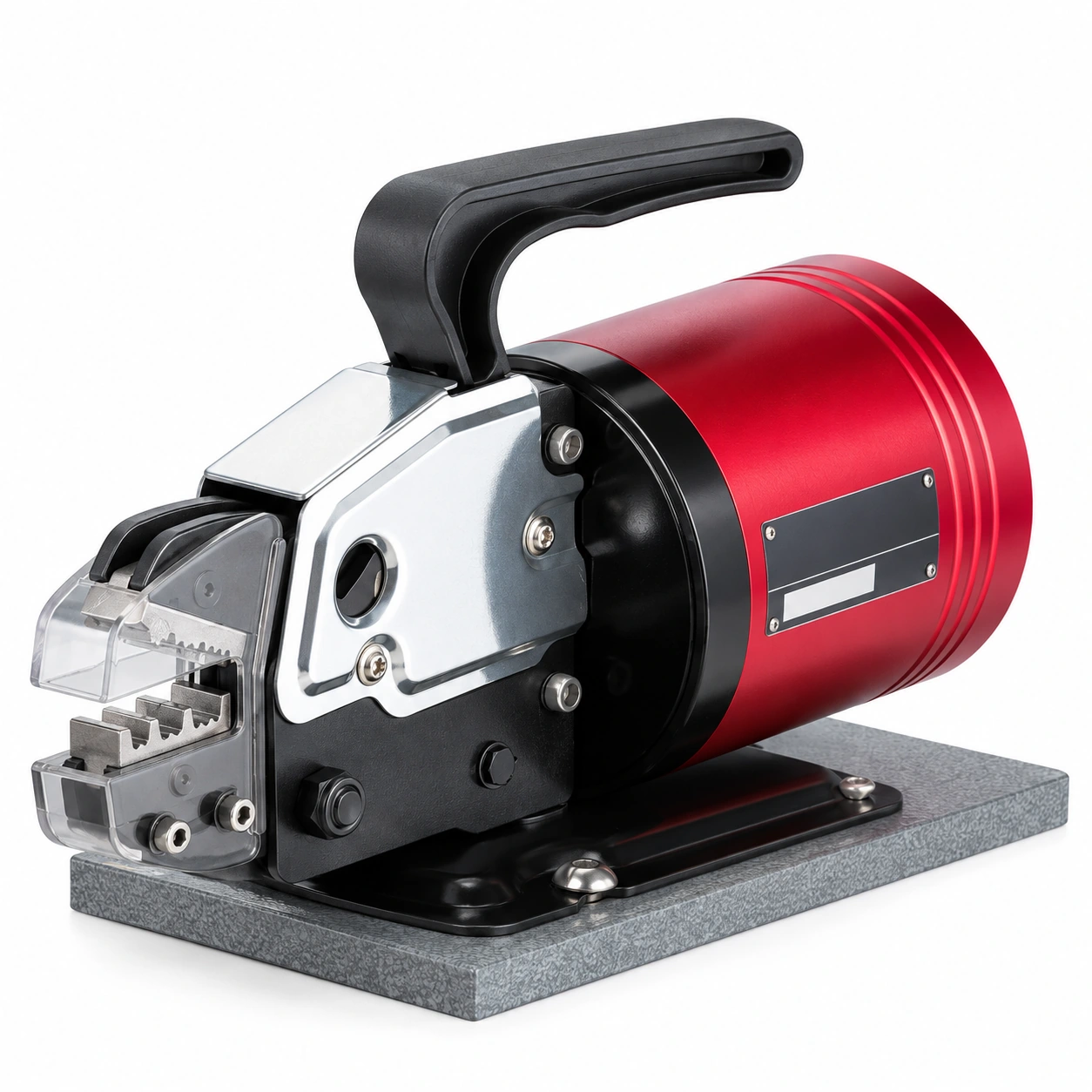
FEK-5ND Pneumatic Crimping Machine
SV.040101
Range: Die-dependent
Output: 1.3 T at 0.5 MPa
Supply: 0.5–0.6 MPa
Weight: 6.0 kg
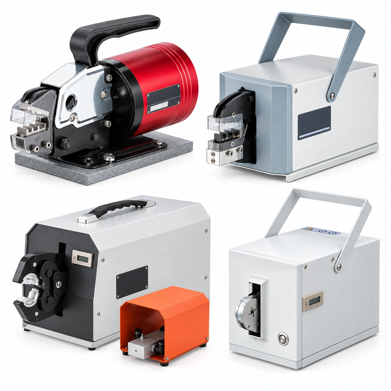
Match the machine and die set to your terminal. Compare eleven pneumatic and electric terminal crimping machines from TONFUL Electric, then confirm conductor size, crimp profile, supply requirements and production needs.
SV.040101
Range: Die-dependent
Output: 1.3 T at 0.5 MPa
Supply: 0.5–0.6 MPa
Weight: 6.0 kg
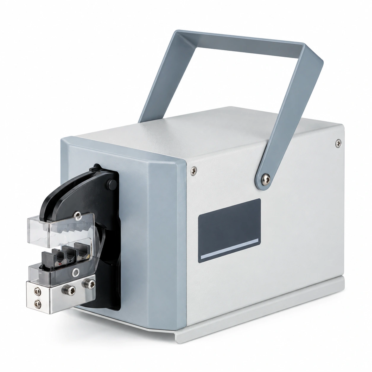
SV.040102
Range: Die-dependent
Output: 2.0 T
Supply: 0.5–0.7 MPa
Weight: 6.0 kg
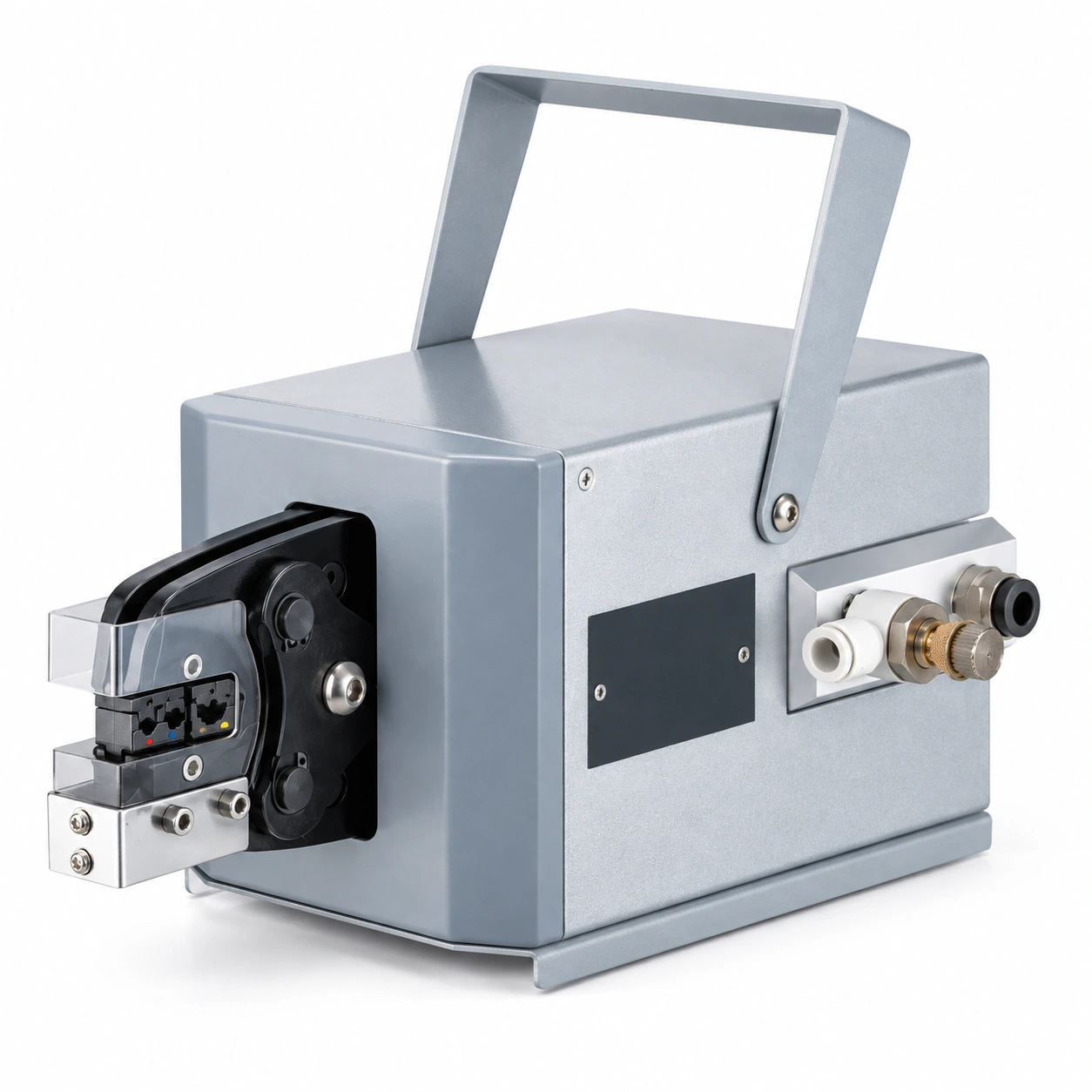
SV.040103
Range: Die-dependent
Output: 2.5 T
Supply: 0.5–0.8 MPa
Weight: 7.0 kg
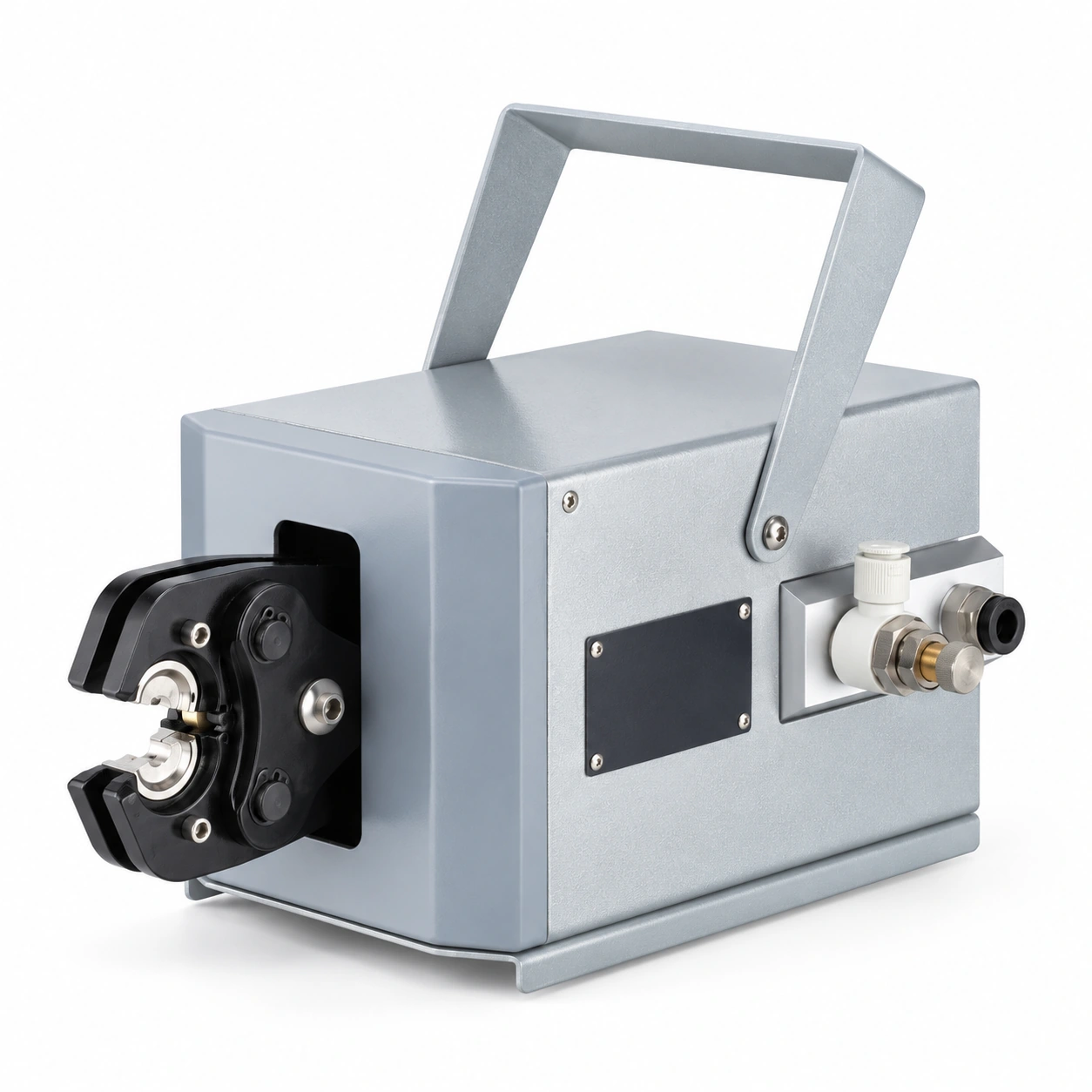
SV.040104
Range: 6–70 mm²
Output: 2.0 T
Supply: 0.5–0.8 MPa
Weight: 7.0 kg
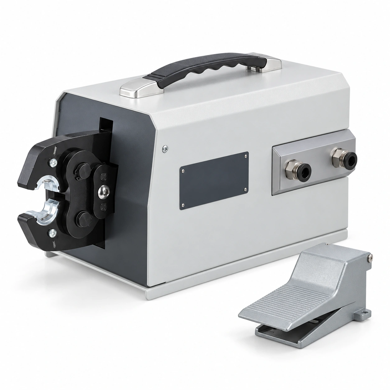
SV.040105
Range: 6–95 mm²
Output: 6.0 T
Supply: 0.5–0.8 MPa
Weight: 11.0 kg
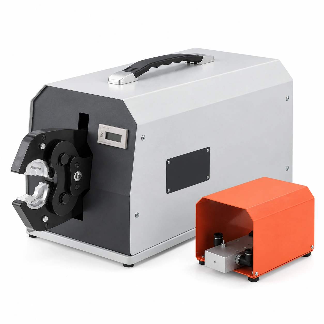
SV.040106
Range: 6–300 mm²
Output: 9.0 T
Supply: 0.5–0.8 MPa
Weight: 17.0 kg
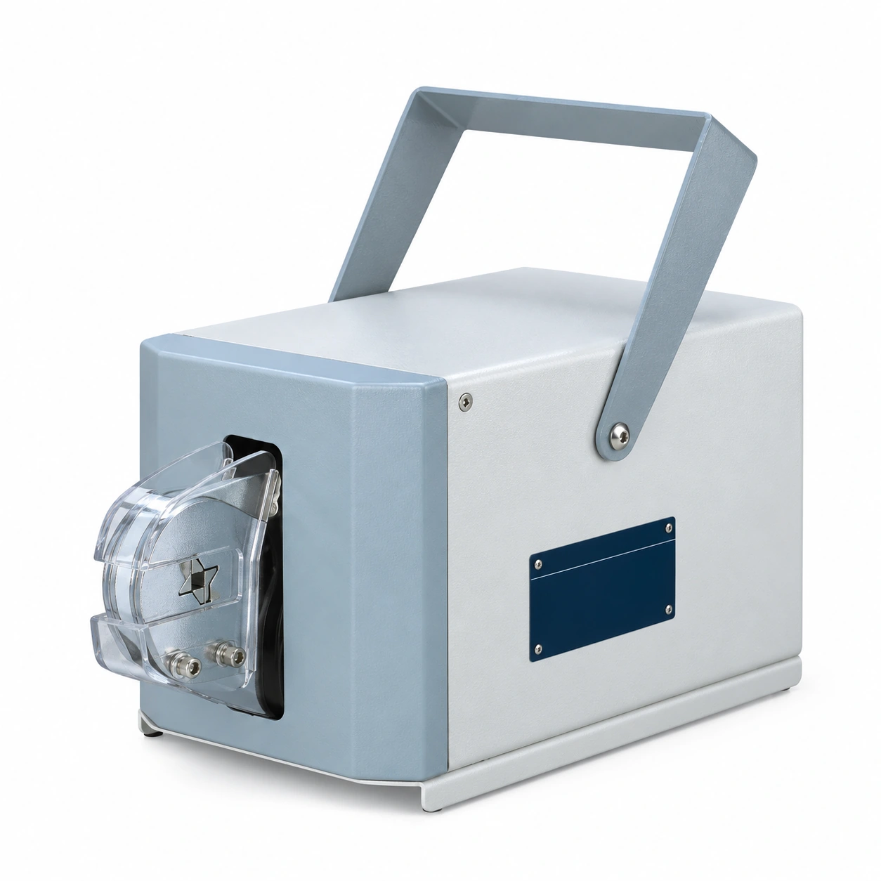
SV.040107
Range: 0.08–10 mm²
Output: 1.2 T
Supply: 0.5–0.7 MPa
Weight: 6.0 kg
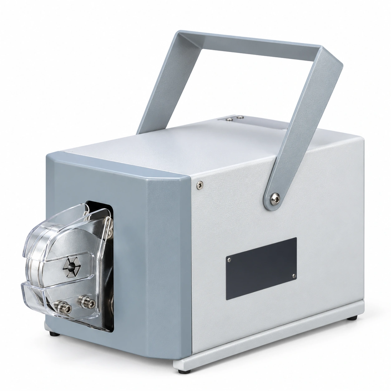
SV.040108
Range: 0.08–6 mm²
Output: 1.2 T
Supply: 0.5–0.7 MPa
Weight: 6.0 kg
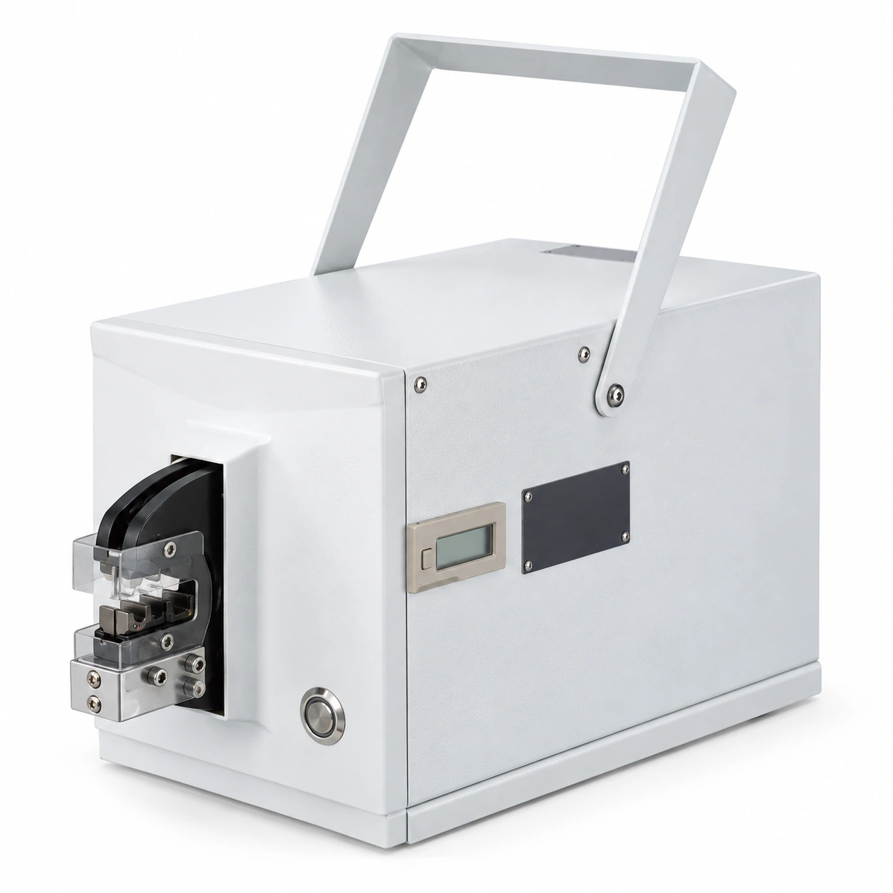
SV.050101
Range: Die-dependent
Output: 2.5 T
Supply: AC 220–110 (catalog)
Weight: 12.0 kg
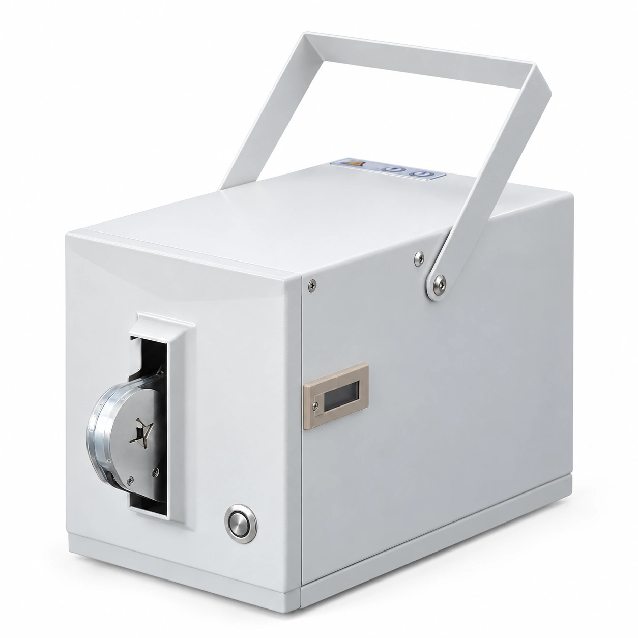
SV.050102
Range: 0.08–10 mm²
Output: 2.5 T
Supply: AC 220–110 (catalog)
Weight: 11.2 kg
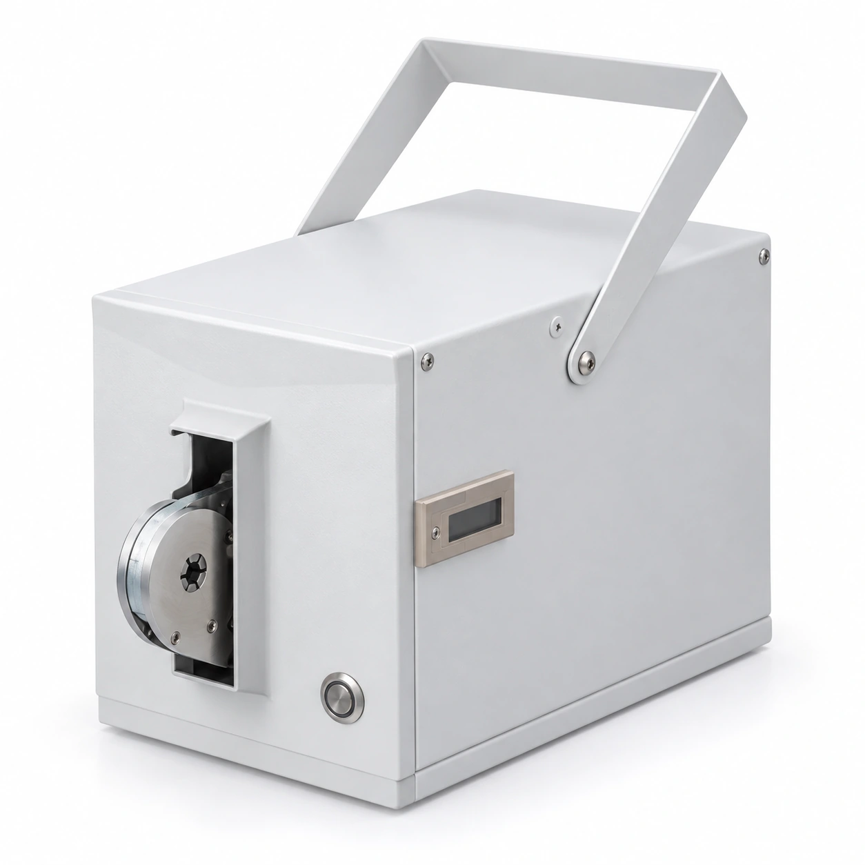
SV.050103
Range: 0.08–6 mm²
Output: 2.5 T
Supply: AC 220–110 (catalog)
Weight: 11.2 kg
Compare pneumatic and electric models, then confirm the required crimping head and die combination.
| Model | Code | Drive | Crimping range | Air / voltage supply | Output (catalog) | Overall size (mm) | Weight (kg) | Package (mm) |
|---|---|---|---|---|---|---|---|---|
| FEK-5ND | SV.040101 | Pneumatic | Die-dependent | 0.5–0.6 MPa | 1.3 T at 0.5 MPa | 230 × 187 × 100 | 6.0 | 340 × 325 × 250 |
| FEK-06M | SV.040102 | Pneumatic | Die-dependent | 0.5–0.7 MPa | 2.0 T | 286 × 125 × 165 | 6.0 | 350 × 240 × 190 |
| FEK-20M | SV.040103 | Pneumatic | Die-dependent | 0.5–0.8 MPa | 2.5 T | 275 × 128 × 145 | 7.0 | 350 × 240 × 190 |
| FEK-50L | SV.040104 | Pneumatic | 6–70 mm² | 0.5–0.8 MPa | 2.0 T | 275 × 128 × 145 | 7.0 | 350 × 240 × 190 |
| FEK-90L | SV.040105 | Pneumatic | 6–95 mm² | 0.5–0.8 MPa | 6.0 T | 330 × 170 × 175 | 11.0 | 580 × 240 × 235 |
| FEK-300L | SV.040106 | Pneumatic | 6–300 mm² | 0.5–0.8 MPa | 9.0 T | 450 × 200 × 220 | 17.0 | 635 × 280 × 285 |
| FEK-6-4 | SV.040107 | Pneumatic | 0.08–10 mm² | 0.5–0.7 MPa | 1.2 T | 286 × 125 × 165 | 6.0 | 350 × 240 × 190 |
| FEK-6-6 | SV.040108 | Pneumatic | 0.08–6 mm² | 0.5–0.7 MPa | 1.2 T | 286 × 125 × 165 | 6.0 | 350 × 240 × 190 |
| FEK-60EM | SV.050101 | Electric | Die-dependent | AC 220–110 (catalog) | 2.5 T | 140 × 220 × 320 | 12.0 | 595 × 255 × 265 |
| FEK-6-4E | SV.050102 | Electric | 0.08–10 mm² | AC 220–110 (catalog) | 2.5 T | 140 × 220 × 320 | 11.2 | 595 × 255 × 265 |
| FEK-6-6E | SV.050103 | Electric | 0.08–6 mm² | AC 220–110 (catalog) | 2.5 T | 140 × 220 × 320 | 11.2 | 595 × 255 × 265 |
Pneumatic supply values are in MPa. Electric catalog voltage is printed as “AC 220–110”; confirm the required voltage configuration before quotation. Output values use the catalog unit T. Dimensions and packing sizes retain the catalog’s original order. Die-dependent models have separate capacity references below.
The following terminal ranges are listed for compatible die selections. Confirm the exact die and terminal geometry for each machine.
| Terminal type | Listed conductor section |
|---|---|
| Ferrules | 0.25–35 mm² |
| Twin ferrules | 2 × 0.5, 1.0, 1.5, 2.0, 2.5, 4.0, 6.0 mm² |
| Insulated ring / fork terminals | 1.0, 2.0, 2.5, 4.0, 6.0 mm² |
| Non-insulated ring / fork terminals | 0.5, 1.0, 1.5, 2.0, 2.5, 4.0, 6.0, 10.0 mm² |
| Male / female receptacles | 1.0, 2.0, 2.5, 4.0, 6.0 mm² |
| Rectangular-connector contact pins | 1.0, 2.0, 4.0 mm² |
FEK-5ND also lists air consumption of 34 L/min and approximately 1,200 operations per hour. Actual cycle performance depends on setup and handling.
FEK-50L lists SC or TO terminals, point crimping 6–50 mm² and surrounding crimping 6–70 mm²; shown die markings are 5.5, 8.0, 11, 22 and 38 mm² as marked on the source illustration. FEK-90L lists point and surrounding crimping 6–95 mm². FEK-300L lists SC or TO terminals and a 6–300 mm² machine range.
| Die | Terminal | Terminal diameter (mm) | Range (mm²) |
|---|---|---|---|
| RN-8W | RNB8 | 7.2 | 6–10 |
| RN-14W | RNB14 | 9.0 | 10–16 |
| RN-22W | RNB22 | 11.5 | 16–25 |
| RN-38W | RNB38 | 13.3 | 35–50 |
| RN-60W | RNB60 | 15.4 | 50–70 |
| RN-70W | RNB70 | 17.5 | 70–95 |
| SC-10W | SC10 | 6.2 | 10 |
| SC-16W | SC16 | 7.1 | 16 |
| SC-25W | SC25 | 8.8 | 25 |
| SC-35W | SC35 | 10.6 | 35 |
| SC-50W | SC50 | 12.4 | 50 |
| SC-70W | SC70 | 14.7 | 70 |
| SC-95W | SC95 | 17.4 | 95 |
| RN-8D | RNB8 | 7.2 | 6–10 |
| RN-14D | RNB14 | 9.0 | 10–16 |
| RN-22D | RNB22 | 11.5 | 16–25 |
| RN-38D | RNB38 | 13.2 | 35–50 |
| RN-60D | RNB60 | 15.4 | 50–70 |
| RN-70D | RNB70 | 17.5 | 70–95 |
| Die | Terminal | Terminal diameter (mm) | Range (mm²) |
|---|---|---|---|
| RN-8W-14W | RNB8 / RNB14 | 7.2, 9.0 | 6, 10, 16 |
| RN-22W-38W | RNB22 / RNB38 | 11.5, 13.3 | 25, 35, 50 |
| RN-60W | RNB60 | 15.4 | 50–70 |
| RN-70W | RNB70 | 17.5 | 70–95 |
| RN-80W | RNB80 | 19.5 | 80–100 |
| RN-100W | RNB100 | 22.1 | 120–150 |
| RN-150W | RNB150 | 26.6 | 150–185 |
| RN-180W | RNB180 | 28.6 | 185–240 |
| RN-200W | RNB200 | 32.6 | 240–300 |
| SC-10W-25W | SC10, 16, 25 | 6.2, 7.1, 8.8 | 10, 16, 25 |
| SC-35W-50W | SC35, 50 | 10.6, 12.4 | 35, 50 |
| SC-70W | SC70 | 14.7 | 70 |
| SC-95W | SC95 | 17.4 | 95 |
| SC-120W | SC120 | 19.4 | 120 |
| SC-150W | SC150 | 21.2 | 150 |
| SC-185W | SC185 | 23.5 | 185 |
| SC-240W | SC240 | 26.5 | 240 |
| SC-300W | SC300 | 30 | 300 |
| RN-8D-14D | RNB8 / RNB14 | 7.2, 9.0 | 8, 14 |
| RN-22D | RNB22 | 11.5 | 22 |
| RN-38D | RNB38 | 13.2 | 38 |
| RN-60D | RNB60 | 15.4 | 60 |
| RN-70D | RNB70 | 17.5 | 70 |
| RN-80D | RNB80 | 19.5 | 80 |
| RN-100D | RNB100 | 22.1 | 100 |
| RN-150D | RNB150 | 26.6 | 150 |
| RN-180D | RNB180 | 28.6 | 180 |
Use the selected terminal drawing and die reference to confirm compatibility; machine capacity alone does not establish every approved combination.
FEK-6-4 and FEK-6-4E list 0.08–10 mm² and four-sided crimps. FEK-6-6 and FEK-6-6E list 0.08–6 mm² and hexagonal crimps. Catalog descriptions specify side insertion, self-adjusting dies, and insulated or non-insulated ferrules. Confirm single or twin ferrule requirements against the selected configuration.
Prepare the selected machine, die and conductor combination before placing an order.
Specify ferrules, twin ferrules, ring or fork terminals, receptacles, contact pins or cable lugs. Provide the terminal drawing.
Send conductor size and required crimp shape: four-sided, hexagonal, point or other specified profile.
Confirm compressed-air pressure for pneumatic machines or the required AC voltage for electric models. Discuss the foot-switch configuration.
Evaluate representative terminal and wire samples. Agree the required crimp dimensions, pull-test criteria and setup instructions.
Share your machine model, terminal drawings, conductor sizes and intended output.
Prepare an enquiryAgree the machine, die set and utility requirements before procurement.
Explore manufacturingList each FEK model, die reference, terminal type and order quantity. Identify optional dies and foot-switch requirements.
Provide conductor construction, cycle needs, available air supply or voltage, workbench space and operator workflow.
Request the selected machine’s current instructions and drawings. Agree sample evaluation and the evidence needed for your assembly.
OEM & PACKING
Build your order around the selected machines, die kits and delivery requirements.
Confirm model, drive type, crimping head, dies, foot switch and utility requirements.
Discuss available branding, machine labels and packaging artwork for the selected configuration.
Confirm accessories, packing dimensions, protective packaging, quantities and destination in the quotation.
FEK-5ND, FEK-06M, FEK-20M, FEK-50L, FEK-90L, FEK-300L, FEK-6-4 and FEK-6-6 are pneumatic models. Pressure requirements vary; compare the model table.
FEK-60EM, FEK-6-4E and FEK-6-6E are electric. Confirm the voltage configuration matching your facility.
No. Match machine capacity, crimping head, die and terminal geometry. Interchangeable-die models require the correct die for the intended terminal.
The 6-4 models use a four-sided profile and list 0.08–10 mm². The 6-6 models use a hexagonal profile and list 0.08–6 mm².
Provide the model, terminal drawing, conductor size, crimp profile, utility supply, die requirements, quantity and packaging needs.