
Overview
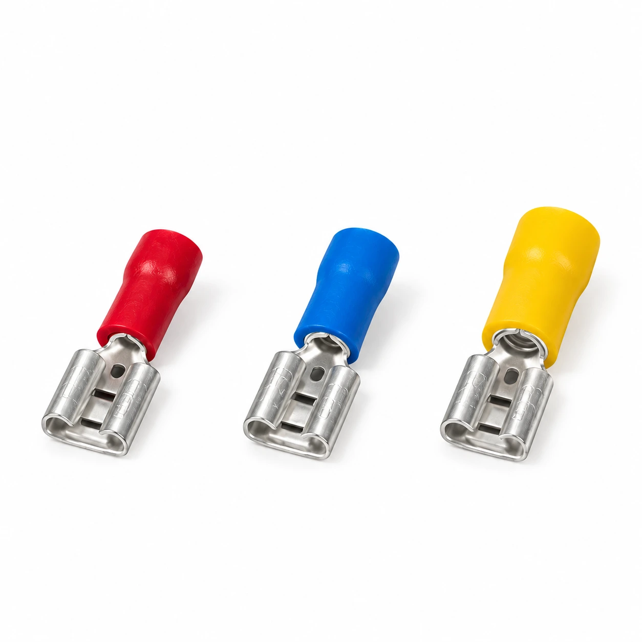
TONFUL Electric FDD Female Insulated Terminal is a vinyl-insulated crimp terminal with an exposed tin-plated brass female quick-disconnect receptacle. The range includes 22 models across three conductor-size groups, with mating tab sizes, current values and dimensions listed below.
Select the female receptacle together with its compatible male tab. Confirm the complete terminal configuration against your drawing or approved sample before ordering.
Features
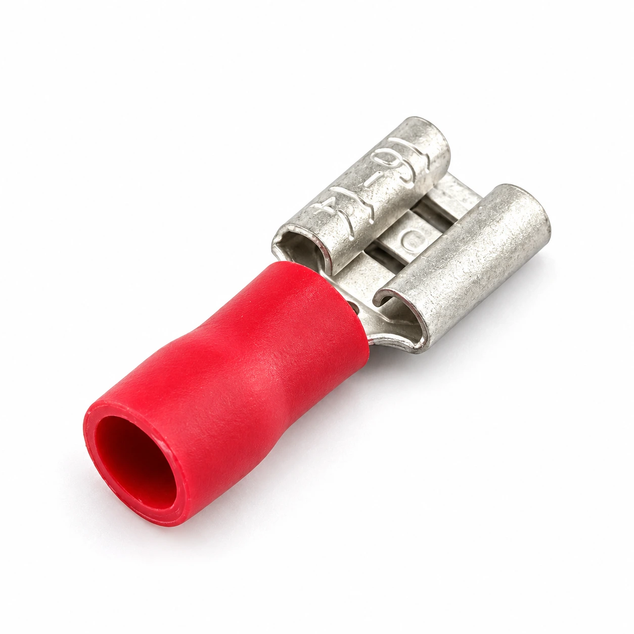
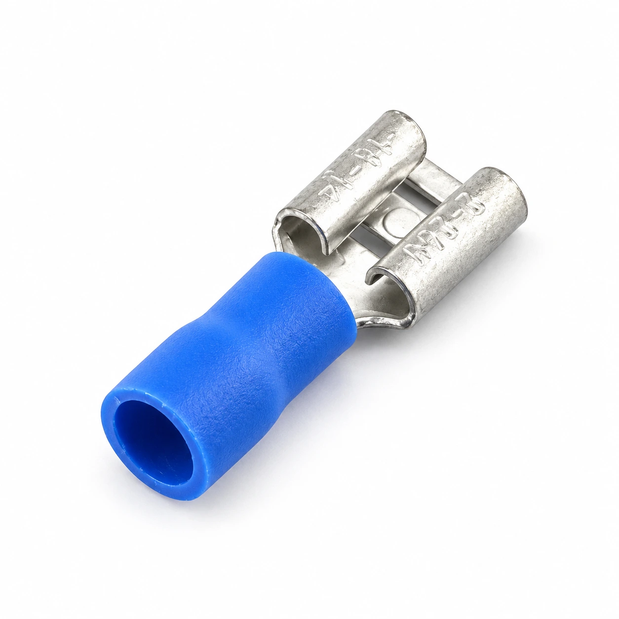
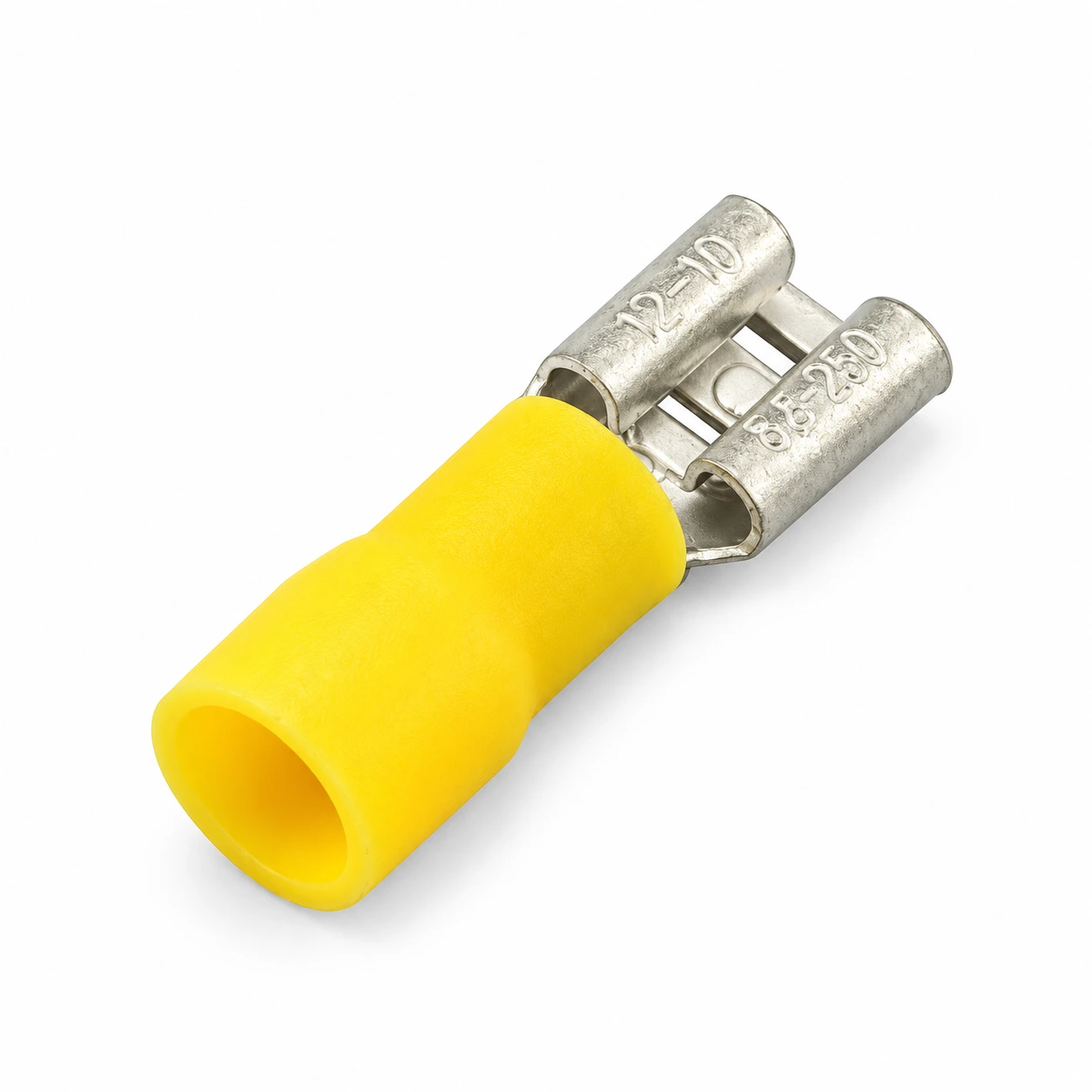
- Vinyl insulation: red, blue and yellow sleeves identify the three listed conductor-size groups.
- Tin-plated brass contact: material and plating retained from TONFUL’s original specifications.
- Female quick-disconnect interface: compare the specified mating tab thickness and width for the intended connection.
- Model-specific selection: conductor range, maximum current and terminal thickness depend on the selected FDD model.
Technical Specifications
| Parameter | Specification |
|---|---|
| Product family | Female insulated quick-disconnect terminal |
| Series | FDD |
| Terminal material | Brass |
| Plating | Tin |
| Insulation material | Vinyl |
| Listed models | 22 |
| Conductor-size groups | 0.5–1.5 / 1.5–2.5 / 4.0–6.0 mm² |
| Maximum current | 10 / 15 / 24 A, depending on model |
Maximum current values are specific to each listed model. Confirm the conductor, mating tab and operating conditions for your assembly.
Dimension
All terminal and mating tab dimensions are in millimeters. The tab column lists thickness × width, as specified on the original product page. Conductor section is shown in mm²; current is shown in A.
| Model | Wire section (mm²) |
AWG | Max current (A) |
Mating tab (mm) |
Terminal thickness (mm) |
B (mm) |
DΦ (mm) |
dΦ (mm) |
L (mm) |
E (mm) |
Color |
|---|---|---|---|---|---|---|---|---|---|---|---|
| FDD1.25-110*5 | 0.5–1.5 | 22–16 | 10 | 0.5×2.8 | 0.3 | 3.3 | 3.8 | 1.7 | 18.5 | 10.0 | Red |
| FDD1.25-110*8 | 0.5–1.5 | 22–16 | 10 | 0.8×2.8 | 0.3 | 3.3 | 3.8 | 1.7 | 18.5 | 10.0 | Red |
| FDD1.25-187*5 | 0.5–1.5 | 22–16 | 10 | 0.5×4.75 | 0.35 | 5.0 | 3.8 | 1.7 | 19.0 | 10.0 | Red |
| FDD1.25-187*8 | 0.5–1.5 | 22–16 | 10 | 0.8×4.75 | 0.35 | 5.0 | 3.8 | 1.7 | 19.0 | 10.0 | Red |
| FDD1.25-205 | 0.5–1.5 | 22–16 | 10 | 0.5×5.2 | 0.35 | 5.7 | 3.8 | 1.7 | 19.0 | 10.0 | Red |
| FDD1.25-250 | 0.5–1.5 | 22–16 | 10 | 0.8×6.35 | 0.4 | 6.6 | 3.8 | 1.7 | 19.8 | 10.0 | Red |
| FDD1.25-312 | 0.5–1.5 | 22–16 | 10 | 0.8×8.0 | 0.4 | 8.2 | 3.8 | 1.7 | 23.0 | 10.0 | Red |
| FDD2-110*5 | 1.5–2.5 | 16–14 | 15 | 0.5×2.8 | 0.3 | 3.3 | 4.3 | 2.3 | 18.5 | 10.0 | Blue |
| FDD2-110*8 | 1.5–2.5 | 16–14 | 15 | 0.8×2.8 | 0.3 | 3.3 | 4.3 | 2.3 | 18.5 | 10.0 | Blue |
| FDD2-187*5 | 1.5–2.5 | 16–14 | 15 | 0.5×4.75 | 0.35 | 5.0 | 4.3 | 2.3 | 19.0 | 10.0 | Blue |
| FDD2-187*8 | 1.5–2.5 | 16–14 | 15 | 0.8×4.75 | 0.35 | 5.0 | 4.3 | 2.3 | 19.0 | 10.0 | Blue |
| FDD2-205 | 1.5–2.5 | 16–14 | 15 | 0.5×5.2 | 0.35 | 5.7 | 4.3 | 2.3 | 19.0 | 10.0 | Blue |
| FDD2-250 | 1.5–2.5 | 16–14 | 15 | 0.8×6.35 | 0.4 | 6.6 | 4.3 | 2.3 | 19.0 | 10.0 | Blue |
| FDD2-312 | 1.5–2.5 | 16–14 | 15 | 0.8×8.0 | 0.4 | 8.2 | 4.3 | 2.3 | 23.7 | 10.0 | Blue |
| FDD2-375 | 1.5–2.5 | 16–14 | 15 | 1.2×9.4 | 0.5 | 9.9 | 4.3 | 2.3 | 27.6 | 10.0 | Blue |
| FDD5.5-110*5 | 4.0–6.0 | 12–10 | 24 | 0.5×2.8 | 0.35 | 3.3 | 5.7 | 3.4 | 21.0 | 12.5 | Yellow |
| FDD5.5-110*8 | 4.0–6.0 | 12–10 | 24 | 0.8×2.8 | 0.35 | 3.3 | 5.7 | 3.4 | 21.0 | 12.5 | Yellow |
| FDD5.5-187*5 | 4.0–6.0 | 12–10 | 24 | 0.5×4.75 | 0.4 | 5.0 | 5.7 | 3.4 | 22.0 | 12.5 | Yellow |
| FDD5.5-187*8 | 4.0–6.0 | 12–10 | 24 | 0.8×4.75 | 0.4 | 5.0 | 5.7 | 3.4 | 22.0 | 12.5 | Yellow |
| FDD5.5-250 | 4.0–6.0 | 12–10 | 24 | 0.8×6.35 | 0.4 | 6.6 | 5.7 | 3.4 | 23.4 | 12.5 | Yellow |
| FDD5.5-312 | 4.0–6.0 | 12–10 | 24 | 0.8×8.0 | 0.5 | 8.2 | 5.7 | 3.4 | 27.3 | 12.5 | Yellow |
| FDD5.5-375 | 4.0–6.0 | 12–10 | 24 | 1.2×9.4 | 0.5 | 9.9 | 5.7 | 3.4 | 29.6 | 12.5 | Yellow |
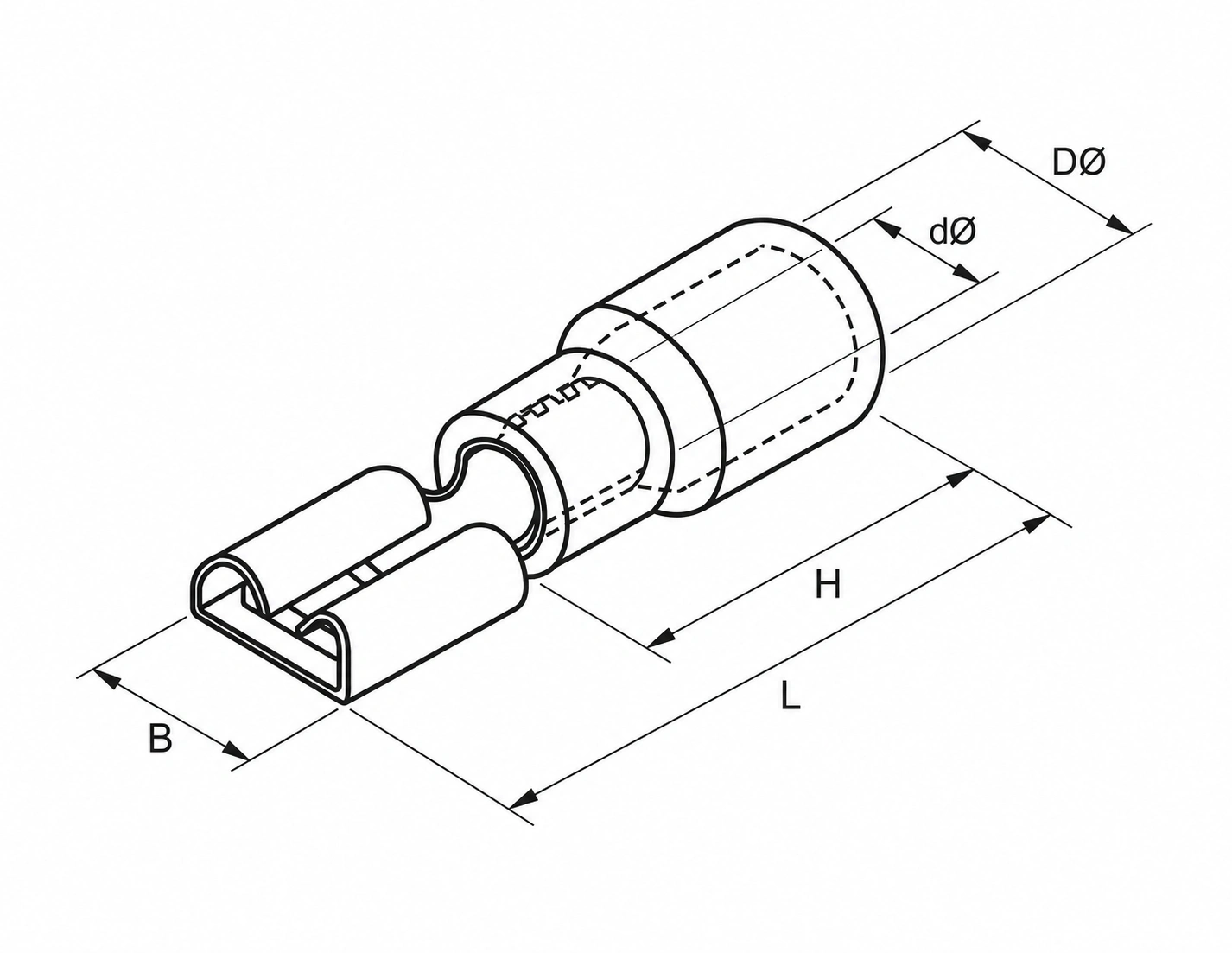
Selection Guide
Start with the conductor section and AWG range. Compare the model-specific maximum current and mating tab thickness × width, then check the listed terminal dimensions. Use a compatible insulated-terminal crimping tool and verify the finished connection against your assembly requirements.
Versions ending in *5 and *8 specify different mating tab thicknesses. Do not select the terminal using sleeve color or tab width alone.
Applications
For crimped wire connections requiring a female quick-disconnect receptacle with a compatible male tab. Potential uses include equipment wiring, cable assemblies and serviceable harness connections where the selected FDD model meets the assembly requirements.
Confirm voltage, temperature, environmental protection and required approvals for the selected product. These ratings are not stated on the original product page.
Ordering Information
Provide the full FDD model number, conductor size, mating tab thickness and width, and order quantity when requesting a quotation. Include sample requirements, packaging preferences and any inspection or documentation requirements.
Explore more vinyl-insulated terminals or TONFUL terminals and connectors.
Product images are high-definition illustrative recreations of the original photographs. Confirm the product configuration against an approved sample.