
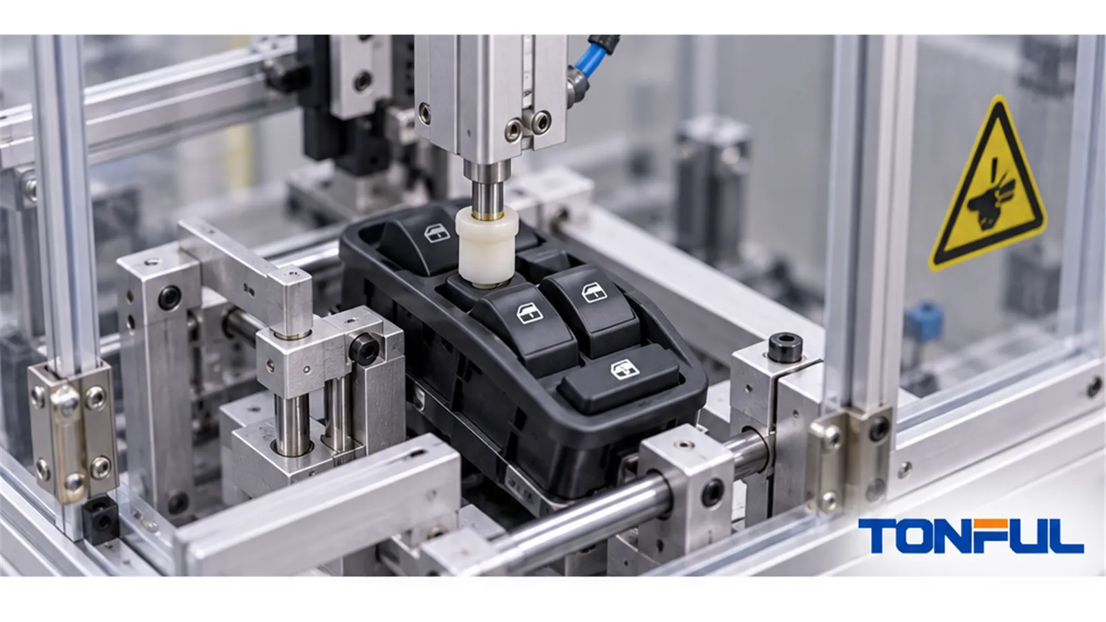
A cycle count alone does not prove power window switch durability. Ten thousand unloaded rocker movements, for example, cannot be compared with the same number of operations under a motor load unless the voltage, current waveform, direction sequence, actuation rate, dwell, temperature, samples, monitoring and failure criteria are also controlled. Even two loaded tests are not comparable when one uses a resistive load and the other reproduces motor startup and interruption.
A useful endurance plan connects the product architecture and customer requirement to a reproducible fixture, recorded baseline, controlled stresses, interim measurements and defined release decision. This guide explains how to build that plan without inventing a universal cycle target, current rating, temperature range or acceptance limit. Every numeric requirement must cite a controlled drawing, customer/OEM specification, applicable standard or approved qualification plan.
On this page: Define Purpose and Samples | Build the Load and Cycle Profile | Monitor Degradation and Investigate Failures | Report Results and Release Production
Define Purpose and Samples
Separate the Test Decisions
“Endurance testing” can support different decisions, and the report should state which one applies:
| Test purpose | Question answered | What it does not automatically prove |
|---|---|---|
| Design qualification | Can the defined design meet the approved life and stress profile? | Future production consistency or every vehicle application |
| Design comparison | How do controlled alternatives behave under the same method? | Compliance when the comparison method differs from the requirement |
| Process validation | Can production-intent tooling and processes build conforming switches? | Unlimited approval after material, site or tooling changes |
| Periodic audit | Does sampled production remain consistent with the control plan? | Every shipped unit passed a full endurance test |
| Failure reproduction | Can a field symptom be recreated and linked to evidence? | Population failure rate without representative sampling |
| Production screening | Can a short test detect specified assembly defects? | Full service-life durability |
Define the decision owner, product and revision, vehicle/application boundary, requirement source and acceptance status before samples enter the fixture. A result must not be reused for another architecture, contact load, software revision or door function without documented engineering justification.
Select and Baseline the Samples
State sample quantity and selection method rather than choosing units that merely look acceptable. Identify each specimen by part number, revision, manufacturing lot, date, tooling or mold cavity where relevant, line, shift and build status. For electronics, include PCB, hardware, firmware and calibration versions. Record whether samples are prototypes, production-intent units or normal serial production.
Baseline inspection should cover housing and connector condition, terminal position, symbols, illumination, rocker force-travel, detents, return, contact or output matrix and every integrated function. For direct-load paths, record initial voltage drop or resistance using the approved method. For resistance-coded or electronic switches, capture each state window, supply current, communication status and DTC behavior.
Preconditioning must be explicit: storage, temperature/humidity stabilization, chemical exposure, vibration, connector mating cycles or prior electrical loading. Define invalid-sample and replacement rules before testing so a damaged setup cannot be quietly replaced with a favorable specimen.

The approved test plan must connect sample identity, actuator geometry, electrical load, environment, monitoring channels and acceptance criteria.
Build the Load and Cycle Profile
Define One Complete Cycle
A cycle must describe every mechanical and electrical action. Record the starting position, direction, first or second detent, actuator travel, applied force, hold time, release, neutral dwell and opposite-direction sequence. If the master switch has four window channels, lockout or door-lock functions, define whether those controls are tested independently, sequentially or in a combined duty profile.
| Cycle field | Required definition |
|---|---|
| Function/channel | Driver, passenger, rear, lockout, illumination or integrated control |
| Direction and stage | UP/DOWN, manual/express, first/second detent and neutral |
| Mechanical input | Actuator tip, angle, alignment, force, travel and speed |
| Timing | Hold, release, neutral dwell, reversal delay and rest period |
| Electrical state | Supply, load, polarity, module/network status and protection |
| Count logic | What increments a cycle and how interrupted cycles are handled |
| Monitoring interval | Continuous channels and scheduled inspection points |
| Stop condition | Failure threshold, safety event, equipment fault or planned completion |
Actuation faster than realistic use can alter contact heating, arc behavior and cooling. Excessive off-time may hide temperature accumulation, while inadequate reversal delay can create an unrealistic motor condition. The approved profile should represent the intended requirement, not simply maximize laboratory throughput.
Reproduce the Correct Electrical Load
First identify whether the switch directly reverses motor current, drives a relay, outputs resistance or voltage codes, or sends LIN/CAN commands. A dry mechanical test evaluates wear and feel but cannot prove powered contact durability. A simple resistive load may not reproduce motor startup, stall or DC interruption.
For a direct motor-current path, define normal running, startup/inrush and any specified stall condition; supply range; polarity; wiring and connector resistance; protection; load simulator or actual motor; contact voltage drop; current waveform; and temperature measurement points. Verify that the fixture and terminals carry the load without becoming the dominant failure source. Do not assume a lower steady current at higher system voltage makes DC switching easier; arc energy, inductance and interruption conditions remain project-specific. The 24V Truck Power Window Switch selection guide explains voltage domains and direct-load evidence in more detail.
For relay, coded or network inputs, monitor the actual output that the controller must interpret. Record resistance windows, loaded signal voltages, message/state data, latency, missing commands, communication errors, sleep/active current and recovery after disturbance as applicable. The Power Window Switch Contact Resistance Testing guide explains measurement boundaries for contact and circuit paths.
Combine Environmental Stresses Only When Required
Temperature, humidity, condensation, dust, chemicals, vibration and supply disturbances may affect wear or signal stability. Define whether they are preconditioning, concurrent endurance stresses or post-test evaluations. Combined testing can reveal interactions, but it can also create an untraceable result if chamber, vibration, load and actuator conditions are not synchronized.
ISO 16750-2:2023 addresses electrical loads, ISO 16750-3:2023 mechanical loads and ISO 16750-4:2023 climatic loads for road-vehicle electrical/electronic equipment. They do not provide one universal power-window-switch cycle count or prove product compliance merely because they are cited. Confirm edition, applicability, severity, sequence, operating mode, sample count and acceptance criteria from the customer/OEM requirement or approved plan. ISO 16750-2 does not cover EMC.
Monitor Degradation and Investigate Failures
Measure Before Total Loss of Function
A switch can degrade long before complete failure. Define baseline, interim and final checks, plus continuous channels where needed.
| Failure evidence | Measurement or observation | Possible investigation path |
|---|---|---|
| Rising voltage drop or resistance | Controlled load, test points, temperature and corrected trend | Contact wear, contamination, reduced force, terminal or connection change |
| Intermittent open/output | Time-correlated waveform or state log | Bounce, worn track, loose terminal, harness/fixture movement or solder fault |
| Contact welding or sticking | Current event, failed-cycle number and teardown | DC arc, excessive load, insufficient contact separation or material damage |
| Temperature increase | Named locations, sensor method, ambient and load | High resistance, overload, connector loss or inadequate cooling |
| Force-travel drift | Curve, detent location, hysteresis and return | Spring relaxation, wear, deformation, lubricant or housing change |
| Resistance-code drift | Every state value and tolerance source | Track wear, contamination, component drift or contact instability |
| Communication error | Message/state capture, timing, DTC and recovery | Supply, software, transceiver, connector or internal electronics |
| Illumination failure | Voltage/current, brightness/color method and visual evidence | LED/component damage, solder fault, thermal stress or driver failure |
| Housing/connector damage | Photographs, dimensions, retention and mating evidence | Fixture overload, temperature, material weakness or terminal heating |
Trend individual samples instead of reporting only an average. An average can hide one early failure or opposing changes. Retain the first-failure cycle, symptom, test state and raw data. If a monitoring limit is exceeded, stop or continue only according to the approved plan so teardown evidence is not destroyed.
Control Invalid Tests, Retests and Interruptions
The plan should distinguish product failure from power loss, fixture misalignment, chamber excursion, sensor fault, software interruption and operator error. Record every interruption with timestamps and affected cycle range. Do not delete data from an invalid event.
Define who may declare a test invalid, whether the same sample can resume, when a replacement sample is permitted and whether the full sequence must restart. A retest cannot erase the original result. Reports should show the initial event, technical justification, authorization and both result sets. Repeated fixture failures require corrective action before more product conclusions are drawn.
Preserve Teardown and Root-Cause Evidence
Do not open a failed switch before documenting external condition, connector, terminals, force-travel, electrical behavior and failure reproduction. During teardown, map contacts, springs, lubricants, resistance elements, PCB/solder joints and debris to the sample and failed function. Use consistent orientation and preserve components needed for material, plating or cross-section analysis.
An endurance failure should link symptom to mechanism and corrective action. “Contact worn” is incomplete without load history, location, material/plating evidence and comparison with passing samples. Permanent action may involve design, material, lubrication, terminal fit, assembly parameter, software, fixture or test-plan changes; verify the change with defined evidence.

Preserve sample identity, failed-cycle data, waveforms, photographs and teardown evidence before assigning root cause.
Report Results and Release Production
Use a Practical Test Record
| Record field | Required entry |
|---|---|
| Test identity | Plan number, revision, purpose, requirement source and decision owner |
| Samples | Part/revision, lot, cavity/line, build status, quantity and selection method |
| Baseline | Appearance, dimensions, force-travel, functions and electrical outputs |
| Fixture | Drawing, actuator geometry, load circuit, equipment IDs and calibration |
| Cycle profile | Actions, rate, dwell, sequence, rest periods and total cycles |
| Electrical load | Supply, load type, running/inrush/stall conditions, protection and wiring |
| Environment | Temperature, humidity, vibration or preconditioning with time records |
| Monitoring | Channels, intervals, raw values, trends, alarms and stop criteria |
| Failure | First cycle, symptom, mode, preserved evidence and teardown result |
| Deviations | Interruption, invalid-test decision, retest authorization and impact |
| Decision | Acceptance source, sample disposition, pass/fail, reviewer and date |
The report should include raw data, summary plots, sample-by-sample results, fixture photographs, calibration status and deviations. A single “Pass” line or repeated “Enter controlled result” cells are not an auditable endurance record.
Connect Testing to Supplier Control
Before production approval, review the process flow, PFMEA, control plan, work instructions and inspection/test records for characteristics linked to endurance risk. These may include contact material/plating, spring force, lubricant, terminal insertion, rocker components, soldering, resistance elements, PCB assembly, firmware and end-of-line coverage. Use measurement-system evidence and process capability only where appropriate to the named characteristic and customer requirement.
Changes to design, material, plating, spring, lubricant, electronics, software, tooling, cavity, process, site, sub-supplier, fixture, test method or packaging require risk review and approval when specified. Define whether endurance testing must be repeated fully, partially or not at all, and document the rationale. Sample approval is not automatic serial-production approval.
The Power Window Switch Manufacturer Audit Checklist supports process review, while the Power Window Switch RFQ and Sample Approval Checklist helps define evidence before quotation and release.
Final Release Checklist
- Test purpose, requirement source and approval boundary are explicit.
- Samples represent the intended design and production status and are traceable.
- Mechanical cycle, electrical load, timing and environment are reproducible.
- Baseline, interim, final and continuous monitoring requirements are defined.
- Failure criteria cite controlled acceptance documents.
- Interruptions, invalid tests, retests and deviations are retained.
- Failed samples have documented teardown and root-cause evidence.
- Production controls and change-notification requirements address endurance risks.
Work With TONFUL
TONFUL’s automotive power window switch range presents current vehicle applications and OE references. For an endurance-testing project, provide the switch application and architecture, product drawing, function matrix, electrical load, cycle profile, environment, sample requirements, monitoring channels, failure criteria and report format. TONFUL can review the applicable product and sample scope; final test acceptance remains tied to the approved customer or project documentation.
