
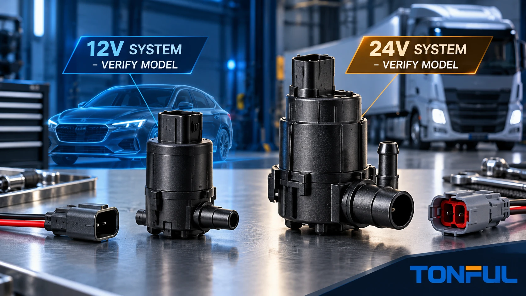
The difference between a 12 V and 24 V washer pump is not just the voltage printed on its body. The correct choice depends on the vehicle’s nominal electrical system, the pump’s approved operating range, control architecture, current and hydraulic load, connector, reservoir interface, protection and vehicle-level performance. A matching housing or plug does not make the two voltage versions interchangeable.
A nominal 24 V truck also does not prove that every terminal in its washer circuit carries 24 V. A switch may provide a low-current request to a body module, while a relay or electronic driver supplies the pump. Conversely, a simple system may switch pump current directly. Identify the circuit before applying power or selecting a replacement.
On this page: Quick comparison | Voltage domains | Electrical load | Misapplication | Validation matrix | Release
12V and 24V Quick Comparison
| Decision area | Typical 12 V project | Typical 24 V project | What must be verified |
|---|---|---|---|
| Vehicle context | Passenger car, light commercial or specified equipment | Heavy truck, bus, off-highway or specified equipment | Actual vehicle architecture, not vehicle class alone |
| Pump supply | Product-specific 12 V domain | Product-specific 24 V domain | Approved operating range and polarity |
| Steady current | Depends on pump and hydraulic load | Depends on pump and hydraulic load | Measured current at defined voltage and restriction |
| Starting/stall condition | Project-specific | Project-specific | Peak current, duration, protection and recovery |
| Control | Direct, relay or module driver | Direct, relay or module driver | Circuit diagram and driver capability |
| Connector | Model-specific | Model-specific | End view, terminals, keying and current capacity |
| Performance | Set by system operating point | Set by system operating point | Flow and pressure under equivalent test conditions |
At equal mechanical output, a higher supply voltage may allow a design with lower current, but that relationship does not prove interchangeability or easier operation. Motor winding, commutation, electronics, suppression, connector and protection are designed as a system. Flow and pressure can also differ between products even when voltage labels match.

Conceptual comparison; use the controlled product specification and vehicle circuit for final values.
Separate Vehicle Voltage From Pump and Control Voltage
Nominal Vehicle Voltage
Passenger vehicles commonly use a nominal 12 V system, while many heavy trucks and buses use a nominal 24 V system. Nominal voltage is a system label, not a constant terminal value. Charging, starting, brownout, load switching, reverse connection and other events can expose components to conditions above or below the nominal number.
The ISO page for ISO 16750-2:2023 describes electrical loads for road-vehicle electrical and electronic equipment. It notes that wiring and connection impedance can affect electrical loads and explicitly states that EMC is outside its scope. The standard does not supply a universal washer-pump operating range or automatically qualify a TONFUL model. Applicable conditions and severities must come from the customer or OEM specification and approved validation plan.
Pump Power Domain
The pump motor or electronic assembly has its own specified voltage range. Confirm the terminal definition, polarity, permitted duty and abnormal-voltage behavior. A two-terminal motor may appear simple, but an electronic or controlled pump can contain protection, suppression or driver circuitry that changes how it responds to reversal and transients.
Do not infer the voltage version from connector color or pump size. Capture the complete label, drawing revision and supplied-part number. If the label is missing, identify the item through controlled records and protected testing rather than applying the vehicle’s nominal voltage experimentally.
Command and Logic Domains
The driver’s washer request may be processed by a combination switch, body control module, relay or dedicated control module. The TONFUL auto combination switch range is relevant to command-side sourcing, but a switch and pump require separate approvals. The wiper switch diagnostic guide can help isolate a command-side complaint before pump replacement. A 24 V vehicle can still use low-voltage logic, resistance-coded inputs or a module-interpreted signal at the switch.
An unidentified command or module pin must never be energized from the nominal vehicle supply. Use the vehicle-specific wiring diagram and approved breakout method. A test lamp suitable for a direct load circuit may overload a sensitive module input; use the specified high-impedance measurement method for electronic circuits.
Compare Electrical and Hydraulic Load Together
Current Depends on the Operating Point
Pump current should be recorded with the test fluid, fluid temperature, voltage at the pump terminals, inlet condition and outlet restriction. Free-flow current and current against the installed nozzles may differ. A partially blocked line, frozen fluid, kinked hose or stalled impeller can change the electrical load and may activate protection or damage the motor.
Do not compare a 12 V pump tested free-flow at room temperature with a 24 V pump tested through a vehicle nozzle at low temperature. Use equivalent fixtures and report the raw conditions. Where a current limit is required, cite the drawing, product specification or customer-approved plan rather than a generic blog value.
Starting and Stall Behavior
An electric motor can draw a transient current when starting and a different current if the rotor stalls. The test plan should define how these states are created, how long they are applied, what protection is present and what constitutes recovery or failure. Do not repeatedly stall an unknown pump during identification.
Circuit protection must coordinate with wiring, connector, driver and load. TONFUL’s automotive blade fuse range can support BOM discussions, but a fuse cannot be chosen solely from the pump’s steady current or vehicle voltage. The time-current characteristic, conductor capacity, inrush and fault behavior all matter.
Hydraulic Performance Is Not Set by Voltage Alone
The pump must deliver the specified flow and pressure at the approved operating point. Applying 24 V to a 12 V pump is not a valid way to obtain more spray. It can overspeed the motor, increase heating, damage commutation or seals and shorten life. Applying 12 V to a 24 V pump can create weak flow, failure to start, unstable operation or excessive duration.
Measure voltage at the pump while it operates, not only at an unloaded harness connector. Harness and contact resistance can reduce terminal voltage under load. The TONFUL automotive electrical connector range may support the mating-interface discussion, but terminal capacity and voltage drop must be verified for the exact connector and circuit.
What Happens When Voltage Versions Are Mixed
| Misapplication | Possible result | Required check |
|---|---|---|
| 12 V pump on a 24 V supply | Overspeed, high current, heating, arcing, seal or motor damage | Stop; verify pump label, winding/electronics and approved range |
| 24 V pump on a 12 V supply | No start, low flow, poor spray or slow operation | Verify undervoltage behavior and hydraulic operating point |
| 12 V relay coil in a 24 V circuit | Coil overheating or rapid failure | Relay coil rating, suppression and driver |
| 24 V relay coil in a 12 V circuit | Failure to pull in or unstable contact | Pickup/dropout behavior under approved voltage |
| Direct motor pump substituted for module-controlled pump | Driver overload, DTC or incorrect operation | Control architecture and load profile |
| Same connector used across voltage variants | Incorrect pump accepted by appearance | Label, part number, keying and controlled record |
| Reversible pump powered without circuit identification | Wrong outlet, short circuit or driver damage | Polarity map and protected test procedure |
If a wrong-voltage pump has been energized, do not assume it remains serviceable because it still runs. Quarantine the sample, document voltage and duration, inspect current and leakage, and follow the approved disposition. Electrical overstress can create latent damage that is not visible in a short functional check.

Conceptual risk matrix; it is not a source of product-specific failure limits.
Interfaces Still Determine Fitment
Two voltage versions can use different connectors, terminal sizes, keying or wire gauges. They can also share a shell while the internal motor or electronics differ. Record the mating face, cavity population, terminal orientation and latch. Verify the pigtail and strain direction after installation.
Reservoir fit remains independent of voltage. Compare inlet stem, grommet bore, reservoir opening, filter, seating shoulder and installation depth. Confirm outlet count, diameter and direction. A correct voltage pump with the wrong grommet can leak; one with the wrong outlet direction can kink a hose.
When a custom mating lead is needed, TONFUL’s custom wire harness capability can be evaluated. The harness drawing should identify wire, terminals, seals, connector orientation, circuit protection and test requirements. Harness approval does not replace pump validation.
Environmental and Endurance Conditions
Commercial vehicles may experience high utilization, vibration, door or cab impacts, temperature variation, contamination and long service intervals. Passenger vehicles can also see severe cold, heat and chemical exposure. Do not use “truck grade” or “automotive grade” as a substitute for a test plan.
ISO 16750-3:2023 covers mechanical loads in its applicable road-vehicle scope, while ISO 16750-4:2023 covers climatic loads. Their existence does not prove a specific washer pump complies. Define mounting location, fixture, sample allocation, sequence, severities and acceptance criteria from the applicable project requirements.
Endurance should reproduce the approved voltage, fluid, hydraulic load, cycle timing and temperature. Record flow or system delivery, current, leakage, noise and condition at initial, interim and final checkpoints. State whether environmental conditioning uses the same samples sequentially or separate groups, and retain an unaged control when the plan requires one.
12V and 24V Validation Matrix

Conceptual validation matrix; equipment, methods and acceptance criteria must be defined by the approved project plan.
| Verification item | Required evidence |
|---|---|
| Vehicle system | Nominal voltage, market, vehicle/chassis and controlled diagram |
| Pump identity | Exact model, revision, label, sample and lot |
| Operating range | Approved voltage range and functional states |
| Control architecture | Direct, relay, module, PWM or other documented method |
| Polarity/direction | Terminal function and outlet response where reversible |
| Current | Test voltage, hydraulic load, fluid, temperature and result |
| Start/stall | Method, duration, protection, recovery and acceptance source |
| Hydraulic output | Flow and pressure at the approved operating point |
| Connector | End view, terminal capacity, keying, latch and voltage drop |
| Reservoir interface | Grommet, inlet, seating, retention and leakage |
| Environment | Applicable electrical, mechanical, climatic and chemical plan |
| Vehicle test | Installed spray, routing, diagnostics and affected functions |
Release the Exact Voltage Version
Release documentation should state the vehicle and application scope, exact pump number, voltage version, connector, grommet, outlets, approved test record and change-notification requirement. A 12 V sample approval cannot be copied to a 24 V sibling without evidence, even when the housings are shared. The same rule applies in reverse.
Receiving inspection should verify labels before functional tests. Separate voltage versions physically in storage and packaging, use distinct barcodes where practical and challenge the mix-prevention process. If a supplier changes motor, winding, suppression component, connector terminal, seal, impeller or test program, require review against the approved change rules.
Discuss 12V and 24V Washer Pumps With TONFUL
Send TONFUL the vehicle and OE reference, nominal electrical system, circuit diagram or control description, connector end view, reservoir and grommet interface, outlet layout, hydraulic requirement, quantity and destination market. TONFUL can compare the request with its documented washer-pump range and prepare the appropriate sample-validation plan. Final release must remain tied to the exact voltage version and tested application.
