
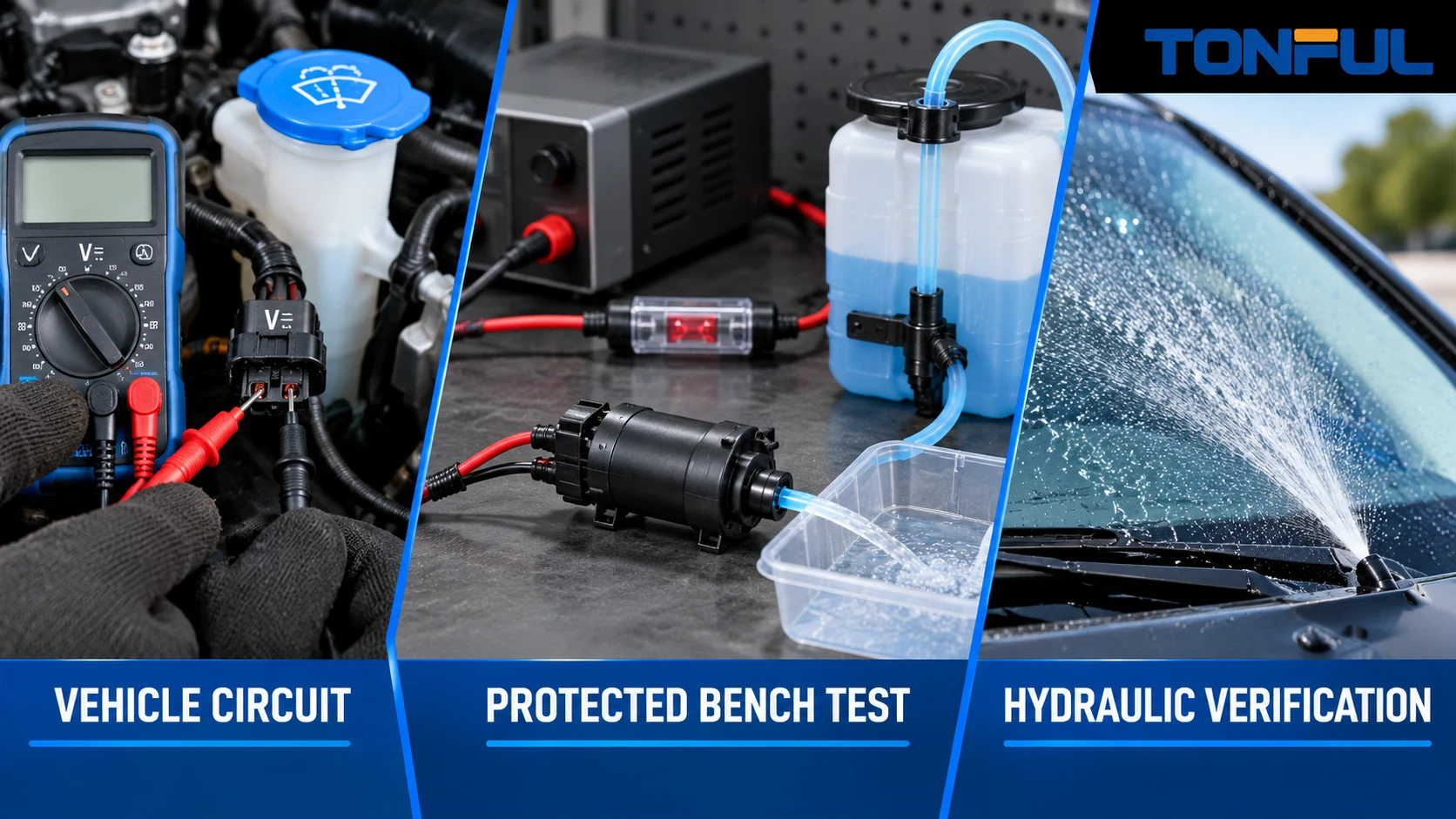
Testing a windshield washer pump safely requires more than connecting two wires to a battery. The pump may be controlled directly, through a relay or by a body control module. Its terminals, polarity and approved voltage must be identified before power is applied. The hydraulic result also depends on fluid, reservoir pickup, hoses, valves and nozzles, so a motor that spins is not automatically a good pump.
Use the vehicle service information and exact product record as the controlling sources. The sequence below separates vehicle-circuit diagnosis, protected bench confirmation and installed-system verification without inventing a universal pinout, fuse rating, voltage-drop limit or flow requirement.
On this page: Safety boundary | Tools | Vehicle test | Bench test | Hydraulic test | Results | Record
Safety Boundary
Secure the vehicle, select the required ignition state and keep hands clear of wiper arms. Automatic wiping, diagnostic commands or a washer request can move the linkage unexpectedly. Follow the manufacturer procedure before removing trim, disconnecting a battery or accessing a module-controlled circuit.
Never energize an unidentified connector cavity. Never use resistance or continuity mode on a powered circuit. Do not use a test lamp on a body-control, encoded or low-current output unless the vehicle documentation explicitly allows it. Avoid piercing insulation or spreading terminals with oversized probes; use the correct breakout lead or back-probing method.
Do not run a pump dry or against an unknown blockage. Toyota owner information warns that continued operation with an empty reservoir can overheat the washer pump. Washer fluid can contain alcohol, so prevent spills near hot surfaces and follow the fluid label and vehicle instructions.
For a removed pump, use only a confirmed power terminal, ground terminal, voltage range and polarity. The bench supply should be fused and current-limited, with insulated leads and a stable fixture. Stop immediately for overheating, smoke, abnormal odor, severe noise, leakage or excessive current under the controlled acceptance plan.

Conceptual illustration only—not an acceptance standard or laboratory micrograph. Vehicle-specific procedures control terminal access and energization.
Tools and Records
Prepare the vehicle diagram, connector view and pump identification before selecting tools. A useful set may include a high-impedance digital multimeter, protected breakout leads, fused current-limited DC supply, current measurement suited to the expected circuit, reservoir fixture, approved fluid, hose, collection vessel, absorbent material and eye protection.
Record instrument model, range, resolution, accuracy and calibration status when the result supports product approval or warranty. Identify the sample, fluid, temperature, supply measured at the pump, hose arrangement and operating duration. A photograph without test conditions is weak evidence.
TONFUL’s automotive electrical connector page is useful when a correct mating connector or breakout harness is needed. The custom wire harness assembly page can support a controlled fixture discussion, but neither replaces the vehicle wiring diagram.
Test the Pump in the Vehicle
1. Confirm Fluid and the Hydraulic Route
Check reservoir level, fluid condition and visible leakage. Inspect the pump seal, accessible hoses and nozzles. If fluid is frozen, contaminated or incorrect, correct that condition before drawing a conclusion about the motor. Do not repeatedly command a blocked or empty system.
2. Observe One Brief Request
Command the affected washer circuit according to the owner or service procedure. Note pump sound, wiper response, spray, leakage and any diagnostic message. If a reversible pump serves front and rear circuits, test each request separately and label which outlet should operate.
3. Check the Fuse and Command Path
Use the vehicle documentation to locate the correct fuse and determine whether a relay or module controls the pump. A fuse that has opened must be replaced only with the specified type and rating after the overcurrent cause is investigated. TONFUL’s blade fuse category provides product context, not vehicle-specific selection authority.
The command can originate in a steering-column switch. The wiper switch diagnostic guide helps separate request-side faults, but switch operation alone does not prove that voltage reaches the pump.
4. Measure Voltage Under Load
Connect the meter using approved test access and select DC voltage. Command the washer briefly while the pump remains connected, where the service procedure permits. Record voltage at the component and the operating condition. An open connector may show nominal voltage but cannot reveal a restriction that appears only when current flows.
Fluke’s automotive voltage-drop guide explains why voltage-drop testing must be performed with current flowing and why test lamps are unsuitable for many computer circuits. Use its measurement principle, but take acceptance limits and test points from the vehicle documentation rather than copying generic values.
If supply and ground are not satisfactory, repair the circuit and retest before condemning the pump. If a module driver is involved, follow its diagnostic routine and scan-tool requirements.

Conceptual illustration only—not an acceptance standard or laboratory micrograph. The meter is in DC-voltage mode; test points and limits must come from controlled documentation.
Protected Bench Test
Remove the pump only after the vehicle procedure is complete and fluid is safely drained or contained. Photograph connector orientation, outlet direction, inlet, grommet and hose routing before disturbance. Inspect the inlet screen or pickup for debris; a blocked inlet can imitate an internally failed pump.
Mount the pump in a stable fixture with the approved inlet submerged or supplied as designed. Connect a known hose and direct discharge into a container. Do not hold the pump by its wires or allow it to move under motor torque.
Set the current limit conservatively according to the known product or test plan, not an invented universal value. Confirm supply polarity before enabling output. Increase only to the documented operating condition while watching current and fluid delivery. Record startup, running current, sound, leakage and flow behavior.
For a reversible dual-outlet pump, test both approved polarity states. Identify Outlet A and Outlet B by physical orientation and final vehicle destination. Confirm that the intended outlet flows and the inactive path behaves within the project requirement. Do not assume terminal function from wire color or another pump with the same shell.
Bench testing proves only the tested pump and fixture. It does not reproduce vehicle wiring losses, long hoses, nozzle restrictions, check valves, elevation or module logic.
Verify Hydraulic Operation
Use a Representative Circuit
Free flow can identify gross operation, but it cannot establish installed performance. Build the approved fixture with representative reservoir, grommet, hose, valves and nozzles. Measure supply voltage at the pump during the hydraulic test.
If flow or pressure is required, state the instrument, range, accuracy, fluid, temperature, restriction and sampling method. Pressure and flow must be evaluated at the specified operating point. Avoid dead-heading a pump unless the approved procedure defines the duration and protection.
Separate Pump Performance From Restrictions
Compare results progressively: pump outlet, hose section, valve and nozzle. A strong outlet result followed by poor nozzle spray points toward downstream restriction or leakage. Low output at the pump with confirmed inlet and electrical supply supports pump investigation. Preserve debris or fluid samples when contamination may be causal.
Use this article’s controlled evidence sequence rather than treating a planned cluster page as proof. TONFUL’s live automotive washer pump category supports sourcing discussions once the exact architecture and interfaces are known.
Interpret the Results
| Test result | Interpretation direction | Next action |
|---|---|---|
| No loaded supply at pump | Fuse, command, relay/module, wiring or ground | Follow vehicle electrical diagnosis |
| Loaded supply acceptable; pump inactive | Motor, terminal contact or internal pump fault | Protected bench confirmation and inspection |
| Pump runs; no outlet flow | Empty/dry inlet, blockage, frozen fluid or internal hydraulic fault | Verify inlet and representative fixture |
| Bench output acceptable; vehicle spray weak | Hose, valve, nozzle, routing or installed supply loss | Segment the vehicle circuit |
| Current abnormal with low output | Restriction, mechanical drag or motor fault | Stop test and inspect under approved plan |
| Front/rear paths reversed | Polarity map, hose routing or incompatible pump | Correct controlled mapping; do not guess |
| Intermittent response | Connector, wiring, module command or internal wear | Capture operating state and repeatable evidence |
Do not decide from one measurement in isolation. Current can be low because a circuit is open, or high because a motor is stalled; it becomes useful only with voltage, hydraulic load and known acceptance criteria. Sound is similarly limited: a rotating motor can coexist with a damaged impeller or blocked path.

Conceptual illustration only—not an acceptance standard or laboratory micrograph. Final disposition requires product- or vehicle-specific criteria.
Installed Verification After Repair
Reinstall the exact approved pump with the correct grommet, connector and hoses. Fill with approved fluid and inspect for leaks before and after operation. Confirm the intended windshield zone receives spray, the pump stops correctly, wiper coordination remains normal and no diagnostic messages appear.
If the vehicle has front and rear washing, test both circuits and inspect the inactive outlet. Move a hatch or tailgate through its range when the rear hose crosses a flexible joint. Record final voltage behavior if the original fault involved supply loss.
Copyable Test Record
| Record field | Required entry |
|---|---|
| Vehicle/sample identity | Vehicle, circuit, pump model, revision and sample ID |
| Controlled sources | Wiring diagram, connector view, test plan and acceptance revision |
| Safety setup | Ignition state, access method, fuse/current limit and spill control |
| Instrument | Model, range, resolution, accuracy and calibration status |
| Fluid/hydraulics | Fluid, temperature, reservoir, hose, valves, nozzle and restriction |
| Vehicle electrical test | Command, loaded voltage, ground result, current and test points |
| Bench test | Supply at pump, polarity, current, duration, outlet and observations |
| Hydraulic result | Flow/pressure if required, leakage, prime and inactive-path behavior |
| Final vehicle result | Spray target, related functions, leaks and diagnostic state |
| Decision | Acceptance source, pass/fail, reviewer and date |
Discuss Washer Pump Testing With TONFUL
Send TONFUL the vehicle and OE reference, removed-pump photos, connector end view, inlet and outlet layout, nominal system, test conditions and measured evidence. TONFUL can review the request against its documented pump range and discuss a sample. Final approval should remain tied to the exact product, controlled test plan and installed vehicle result.
