
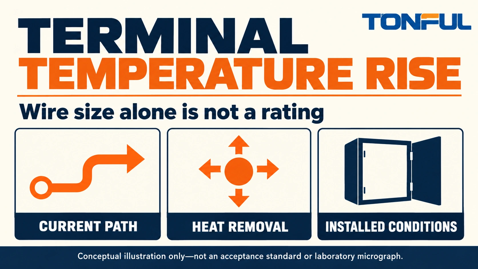
Terminal temperature rise depends on the complete current path and the way heat leaves that path. Wire size matters, but it does not establish the temperature of a crimp barrel, mating contact or bolted joint. Two assemblies using the same nominal conductor area can operate differently because their contact resistance, ambient conditions, enclosure, adjacent circuits and mounting differ.
For engineers and buyers, the right output is a configuration-specific thermal evaluation. Define the load, terminal and wire, installation geometry, measurement method and acceptance source before testing. A conductor-size chart or a catalog current statement cannot replace those details, and an uncontrolled bench experiment is not a product rating.
Jump to: Heat generation and removal | Configuration checklist | Thermal test plan | Temperature rise records | Investigating a hot terminal | Application release
Heat generation and removal
The terminal is part of the electrical path
Resistive heating depends on current and resistance; the familiar relationship is power equals current squared multiplied by resistance for the defined path. That relationship explains why an increased contact resistance can matter, but it does not directly predict terminal temperature. Temperature also depends on heat transfer, material properties and the surrounding assembly.
A crimp connection, mating interface and conductor segment can each contribute losses. Do not assume that a larger wire corrects a damaged contact or wrong tool setup. It can change the thermal behavior of a test assembly while leaving the underlying connection defect unresolved. Likewise, a correctly formed crimp does not establish the suitability of a nearby mating interface.
Heat must leave the connection
Heat can flow into conductors and connected metal, and from surfaces into surrounding air and nearby structures. Enclosure size, orientation, airflow, neighboring loads and mounting therefore matter. Weidmuller’s current-carrying capacity explanation describes the relationship between ambient temperature, self-heating, component limits and configuration. Its discussion supports the principle, not a universal derating curve for every crimp terminal.
Thermal evidence for one product family should not be copied to another. A terminal block, a free-hanging splice and a ring terminal on a busbar have different heat paths. Use the actual product’s approved data or a qualification plan for the intended assembly, rather than transferring a convenient temperature-rise limit from a related catalog page.
Configuration checklist
Freeze the specimen before comparing results
Record the wire material, cross-section, stranding, insulation system and free length. Identify the terminal part number, revision, finish and connection geometry. For a mated pair, record both halves; for a stud connection, identify the joint hardware and assembly instruction. These are test variables, not minor details to reconstruct afterward.
TONFUL’s non-insulated terminal category can help identify exposed terminal architectures for review. If an insulating sleeve is used, record the exact construction. The nylon-insulated terminal family does not share one universal thermal rating merely because the insulation polymer has the same name.
| Variable | What to record | Why it affects interpretation |
|---|---|---|
| Electrical duty | Current, waveform and duty cycle | Determines actual loading |
| Conductor | Material, area, length and routing | Changes losses and heat flow |
| Connection | Terminal, mating part and assembly process | Defines the contact system |
| Environment | Ambient, enclosure and airflow | Defines cooling conditions |
| Adjacent circuits | Number, position and simultaneous load | Adds local heating |
| Mounting | Orientation, supports and connected metal | Changes thermal paths |
| Measurement | Sensor locations and stabilization rule | Defines reported temperature |
Include the actual installed load pattern
One energized circuit in open air may not represent several adjacent circuits operating inside a cabinet. Record which circuits carry current simultaneously and whether nearby equipment adds heat. A qualification program should cover the intended demanding configurations or provide a justified engineering basis for the selected cases.
For intermittent service, define the duty cycle and the required observation window. A short run that ends before the relevant thermal condition is reached cannot be described as a steady-state result. Conversely, an intermittent application may require a defined repeated-cycle evaluation rather than an arbitrary continuous-current test.
Thermal test plan
Establish acceptance before energizing
Name the applicable product, equipment, customer or qualification document and its revision. Define allowable rise, absolute temperature limits and any material or interface constraints through those sources. There is no single temperature-rise number that approves every terminal, wire combination and application. Do not derive a rating by increasing current until a sample appears too hot.
The test should be designed and performed by qualified personnel using approved guarded equipment. Control current, provide appropriate protection and emergency shutdown, and isolate power before changing specimens or sensor positions. Do not touch a suspected hot connection to judge its temperature. Follow equipment and site procedures, especially where stored energy is present.
Choose instrumentation for the decision
Specify current-source capacity and accuracy, current measurement, temperature-channel range, accuracy, calibration status and acquisition interval. Select sensor type and attachment method suitable for the terminal size and required method. Sensor attachment can influence local heat flow; document it and keep it consistent across comparison samples.
Infrared imaging can help locate temperature patterns, but reflective metal and uncertain emissivity can mislead absolute readings. Use the method approved for the acceptance decision and document emissivity treatment, viewing access and reference checks where relevant. A colorful thermal image alone does not establish a calibrated terminal temperature or prove the hottest internal location.

Define sampling and stabilization
Set sample quantity and configuration coverage in the approved plan. Record terminal and wire lots, tooling and assembly operator or process identifier. Include justified boundary configurations rather than assuming that one convenient wire size represents every allowed combination. A small trial can support development but should not be relabeled as full qualification without the required scope.
Define how thermal stabilization is recognized, how ambient is monitored and how interruptions are handled. Place the ambient reference according to the method so that it represents the intended environment rather than direct heating from the specimen. Record actual current and ambient throughout the run, not only nominal settings at startup.
Temperature rise records
Preserve rise and absolute temperature
Temperature rise is the difference between the measured location temperature and its defined ambient reference. Record both source values with units and time alignment. A rise result alone can hide an excessive absolute temperature in a hot enclosure; an absolute temperature alone can hide a different ambient condition between comparison runs.
| Record field | Information to enter |
|---|---|
| Specimens | Terminal, mating part, wire, lots and sample IDs |
| Preparation | Strip/crimp instruction, tool, cavity and assembly settings |
| Installation | Enclosure, orientation, wire length and adjacent loads |
| Electrical duty | Actual current, waveform, cycle and protection |
| Instrumentation | Sensor map, attachment, accuracy and calibration IDs |
| Environment | Ambient reference location, airflow and initial condition |
| Time history | Temperature channels, current, ambient and stabilization |
| Acceptance | Document revision, rise and absolute-temperature criteria |
| Comparison | Initial/aged configuration and any resistance change |
| Disposition | Results, anomalies, invalid tests, retests and approver |
If the program includes aging or environmental conditioning, keep initial and aged data under the same sample identities. Record the conditioning sequence and any recovery period. Compare temperature behavior only with the same load and configuration, or explicitly state the intended difference. Do not attribute a change to aging if the enclosure or wire length also changed without control.
Add electrical measurements only with a defined method
Resistance or voltage-drop checks can help interpret thermal behavior. Define the current, equipment range and accuracy, compensation method and Force/Sense positions. Kelvin sensing removes current-lead drops outside the Sense boundary, not every contribution inside it. Document reference-wire length and any required wire-resistance subtraction at a stated temperature.
Do not substitute a continuity buzzer for those measurements. If mechanical testing is included, define the fixture, loading direction, speed and acceptance source separately; destructive testing normally requires a planned sequence. The thermal report should identify which samples remain intact and which were consumed in later analysis.

Investigating a hot terminal
Start with containment and evidence
Isolate the equipment using the authorized procedure, hold affected assemblies and preserve the original configuration. Record the operating duty, ambient, location and traceability before dismantling. A scorched sleeve is a symptom; it does not by itself identify whether the initiating cause was overloading, contact damage, wrong wire, poor crimping or an installation problem.
Review the measurement method and load first, then inspect wire preparation, crimp geometry, mating engagement, hardware and contamination. Where needed, perform controlled resistance, mechanical or section analysis using approved methods. TONFUL’s crimping tool information can support a tool-compatibility discussion, but changing the tool without confirming the cause is not root-cause closure.
Confirm the cause and update the control plan
Use controlled comparisons to test the suspected mechanism. Keep wire, current, fixture and ambient constant while examining the relevant variable. If a routing problem restricts cooling, revise the installation drawing; if a wrong cavity caused the defect, correct tool identification and setup verification. Confirm effectiveness on representative assemblies before restarting unrestricted production.
Treat invalid tests explicitly. A detached sensor, interrupted current or lost data channel may invalidate a run under the agreed rules. Retain the event and authorize the retest; do not classify a valid hot result as invalid merely because another sample runs cooler. For safety-critical systems, use the equipment manufacturer’s escalation and repair process rather than generic retermination advice.
Application release
Review a change in neighboring loads
Suppose an enclosure revision adds continuously loaded circuits beside an already approved terminal. In this hypothetical review, the terminal and wire size have not changed, but the local thermal conditions have. Compare the revised load arrangement, spacing and airflow with the original approval scope. Determine whether the existing evidence covers the new configuration or whether a targeted thermal evaluation is required.
Do not treat the original bench current as an unconditional installed rating. Preserve the earlier configuration and its limits, then document the revised decision separately. If routing or spacing is changed to control temperature, make those features part of the released installation drawing and inspection plan. Otherwise, a successful development setup can be lost when production returns to a denser arrangement that was never evaluated.
Tie the decision to its configuration
A thermal release should state the approved terminal/wire combination, installation conditions, duty and acceptance-source documents. Identify changes that require review, including enclosure, neighboring load, conductor construction, insulation, finish, tooling and hardware. The same nominal gauge does not make a changed assembly thermally equivalent.
For ferruled panel wiring, include the cord end terminal and receiving-terminal configuration; the ferrule alone is not the thermal system. Send TONFUL the actual connection drawing, load profile, ambient range and test requirements through the wire terminal sourcing page. Request exact product data and samples for a defined evaluation, rather than asking for an unsupported current rating based only on wire size.