
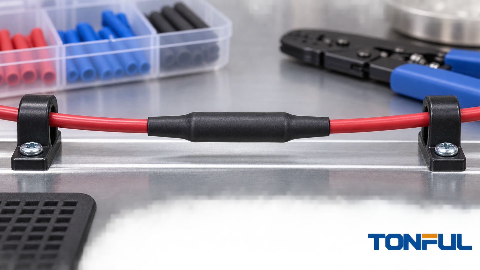
Heat shrink tubing can insulate and protect a wire splice only when the splice itself is approved, the sleeve fits the complete geometry and both ends terminate on suitable insulation or cable jacket. Sleeve length is therefore not simply “splice length plus a standard allowance.” It depends on the connector or joint, conductor insulation, diameter transition, sealing design, longitudinal change, routing and the electrical and mechanical evidence required by the project.
The tubing also has a defined boundary. It cannot repair a poor crimp, restore cut conductor strands, correct the wrong splice size or make an unqualified joint acceptable. It may add insulation, environmental protection and controlled support, but it should not be treated as the sole structural member carrying harness loads unless the approved design explicitly establishes that role.
Define the Splice Before Choosing the Sleeve
Record the splice construction and installation environment. A closed-barrel crimp splice, open-barrel splice, soldered joint, heat-shrinkable soldering device and shielded-cable repair have different shapes and qualification needs. Confirm conductor material, wire construction, insulation, wire size on each side, splice part number, tool and application specification.
| Splice characteristic | Why it changes tubing selection |
|---|---|
| Maximum barrel or joint diameter | Determines pass-over clearance |
| Smallest wire insulation OD | Determines recovered fit at each end |
| Equal or unequal wire sizes | Creates symmetric or asymmetric recovery |
| Sharp barrel edges or wings | Can concentrate stress or damage tubing |
| Seal, shield or branch geometry | May require a purpose-designed assembly |
| Installation sequence | Determines whether tubing can be positioned before termination |
| Temperature and fluids | Affect material and adhesive selection |
| Flexing and support | Affect splice location and transition design |
Do not cover the splice before required visual, dimensional, pull, electrical or other inspections are complete. Once opaque tubing is recovered, important evidence may be hidden. The work instruction should define hold points and who authorizes covering.
Calculate Sleeve Length From Functional Zones
Break the finished sleeve into three zones: coverage over the splice body, transition zones, and overlap on sound insulation or jacket. The required cut length must also account for product-specific longitudinal change during recovery and any positioning tolerance.
Cut length = required finished coverage adjusted for longitudinal change and process tolerance
This is a planning relationship, not a universal numeric formula. Use the tubing drawing or test data for longitudinal change. If the product may shorten, a cut piece equal to the desired finished coverage can expose an edge after shrinking. If the product grows or shifts under the process, it can intrude into a bend, connector seal or inspection feature.
Mark the intended center and sleeve ends during process development. Test the shortest permitted cut length on the largest splice geometry and the full range of wire diameters. Record final position at both ends, not only total sleeve length.

Conceptual illustration only—not an acceptance standard. Final sleeve length and each overlap zone must come from the approved drawing and validated process.
Determine Overlap on Each Side Separately
Overlap is the recovered length that contacts undamaged wire insulation or cable jacket beyond the splice transition. Adequate overlap helps maintain electrical coverage, distribute the stiffness transition and, for adhesive-lined designs, create a sealing land. However, more overlap is not automatically better. Excess length can increase stiffness, conceal damage, interfere with routing or extend into a flex zone.
Evaluate left and right sides independently. A step-down splice, different insulation types or an off-center barrel can need asymmetric design treatment. The overlap surface must be clean, compatible and dimensionally suitable. Adhesive flow on one side does not prove a complete seal on the other.
The heat shrink tubing sizing guide explains why expanded and recovered diameters must both be checked. For a splice, confirm that the unshrunk tube clears the largest barrel feature while the fully recovered ID fits the smallest insulation OD. Avoid selecting solely by nominal wire gauge.
Select Single-Wall or Adhesive-Lined Construction
Single-wall tubing can provide electrical insulation and abrasion protection where environmental sealing is not required. Adhesive-lined or dual-wall tubing can add a seal when the liner is compatible with the substrates and the installation creates continuous coverage. The single-wall versus dual-wall comparison outlines these different functions.
An adhesive bead at the sleeve edge is only one observation. It does not prove that adhesive filled every internal void or bonded to contaminated insulation. Define surface preparation, permitted cleaner, heating sequence, adhesive-flow expectation, cooling and inspection. If water can migrate along conductor strands or under a cable jacket, an outer sleeve may not stop the internal path.
For marine or wet applications, use project-approved components and system-level evidence. The marine heat shrink tubing guide explains why product labels such as “marine grade” do not replace wire, connector, sealing and installation validation.
Treat Strain Relief as Load Management
Heat shrink tubing can smooth a transition and reduce local movement, but it does not automatically create verified strain relief. Loads can still reach the splice through conductor tension, bending, vibration, harness weight or service handling. A sleeve may move the highest bending stress to its edge rather than eliminate it.
Define the load path from the wire to clamps, ties, backshells or other supports. Keep the splice out of repeated-flex areas and avoid placing a sleeve end at the point of maximum bending. Confirm routing after assembly because the recovered sleeve changes local stiffness and bend behavior.
NASA-STD-8739.4A is one authoritative example of application-specific splice controls. It requires covered splices to meet or exceed the electrical isolation defined in engineering documentation, calls for staggered splices to reduce bundle buildup, prohibits splices in flexing areas or bend radii where insulation may be compromised, and controls proximity to breakouts. It also requires splice type and location to be defined on drawings. These provisions apply when that NASA standard governs the work; they are not universal dimensions for other projects. See the official NASA-STD-8739.4A Change 4 document.

Conceptual load-path diagram only. Harness supports and bend restrictions must follow the applicable drawing and installation specification.
Plan the Installation Sequence
Slide the tubing onto the wire before completing the splice when the finished connector cannot pass through it. Position the sleeve far enough from soldering or crimping operations to prevent premature recovery or contamination. Protect it from sharp edges, flux, oil and tool damage.
After the splice passes required inspection, center the sleeve using approved marks or a fixture. Apply heat with equipment suitable for the tubing and surrounding components. Move the heat source to recover the sleeve uniformly rather than overheating one location. For adhesive-lined products, follow the specified recovery sequence so air and excess adhesive are not trapped.
NASA also notes that adjacent components, wires and structures must be protected from the heat source during applicable splice installation. The general lesson is broader: identify heat-sensitive insulation, seals, sensors, optics, coatings and plastics before heating. Do not use an open flame around a harness. The high-temperature automotive heat shrink guide further explains why service temperature and installation temperature are separate requirements.
Allow the assembly to cool without pulling, bending or repositioning the sleeve. Handling while the polymer or adhesive is soft can create movement, thin spots or a distorted seal.
Inspect the Recovered Splice Sleeve
Inspect all sides under the specified lighting and magnification. The final sleeve should be in the drawing-defined position and free of damage that violates acceptance criteria. Do not use a photograph in this article as an acceptance standard.
| Inspection item | Evidence to record | Typical concern to investigate |
|---|---|---|
| Sleeve identity | Part, size, color and lot | Wrong material or mixed lot |
| Final position | Both end locations and coverage | Exposed barrel or shifted overlap |
| Recovery | Fit around both wire diameters | Loose end or bridging |
| Surface | Wrinkles, splits, bubbles and scorching | Sizing, contamination or excess heat |
| Adhesive | Required edge flow and continuous seal evidence | Cold spot, void or incompatibility |
| Wire insulation | No heat or tool damage | Overheating or sharp transition |
| Routing | Bend, support and clearance | Sleeve edge in flex zone |
| Hidden splice record | Completed pre-cover inspection | Missing crimp or electrical evidence |
The guide to heat shrink splits, wrinkles, bubbles and seal failures helps organize defect investigation. Quarantine affected assemblies and examine material identity, cut length, sizing, surfaces, heat profile and operator method rather than reheating every defect.

Inspect the complete circumference and both sleeve ends against the controlled acceptance source.
Validate the Completed Assembly
Validation should address the complete production-intent splice, not tubing alone. Define sample quantity, wire and splice variants, material lots, conditioning sequence, equipment, acceptance criteria, invalid-test rules and reporting before testing.
Depending on the project, the plan may include initial electrical checks, dielectric or insulation tests, pull or mechanical tests, flexing or vibration, thermal cycling, fluid exposure, humidity or immersion, and post-conditioning electrical and visual inspection. Not every test applies to every splice. Values and sequences must come from the product drawing, customer specification, applicable standard or approved qualification plan.
For destructive testing, allocate separate samples or document the approved sequence. Preserve an unaged reference when comparison is needed. Record failure location: conductor, crimp, splice body, insulation, adhesive interface, tubing or support. A result described only as “failed” does not guide corrective action.

A controlled workflow connects splice definition and dimensional design to assembly validation and release evidence.
Use a Splice Sleeve Design Record
| Record field | Required entry |
|---|---|
| Assembly identity | Harness, drawing revision, splice ID and location |
| Conductors | Material, construction, gauge/area and insulation OD each side |
| Splice | Part number, range, tool, die/cavity and application document |
| Tubing | Family, size, ratio, wall, liner, lot and drawing |
| Geometry | Maximum pass-over and minimum recovery surfaces |
| Length design | Splice zone, transitions, overlaps and cut tolerance |
| Process | Heat equipment, controlled settings, sequence and cooling |
| Support | Clamp locations, bend limits and load path |
| Inspection | Pre-cover hold point and post-recovery results |
| Validation | Sample IDs, test plan, results and acceptance source |
| Approval | Deviation, reviewer, disposition and date |
Work With TONFUL
TONFUL can review heat shrink tubing requirements for approved wire-splice applications. Provide the conductor construction and insulation OD on both sides, splice drawing, maximum joint diameter, required finished coverage, environment, sealing need, routing, support method and validation documents. TONFUL can then discuss candidate materials, sizes, cut lengths and samples. Final overlap, strain-relief function, electrical isolation, sealing and performance must be established by the controlled assembly design and project approval rather than assumed from tubing appearance.