
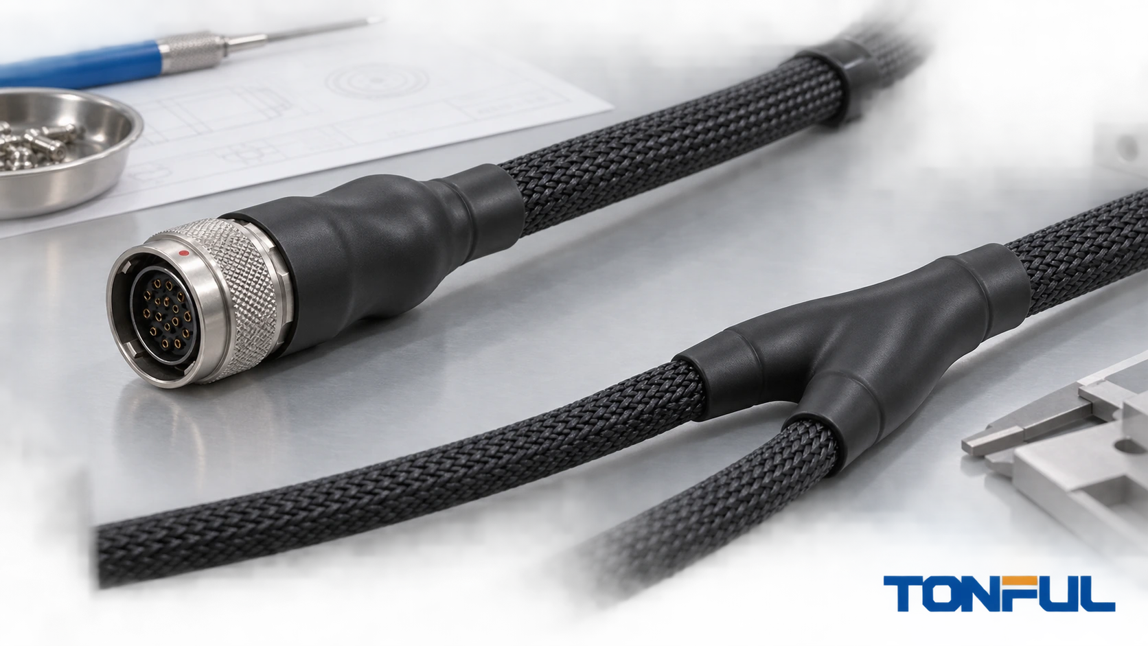
Heat-shrinkable products can protect the transition between a connector and cable bundle or organize a harness where one trunk divides into branches. The correct product may be straight tubing, a molded boot, a multi-leg breakout shape, a shield-termination accessory or a complete backshell system. These parts are not interchangeable simply because they shrink under heat.
Selection begins with connector geometry and the function assigned to the part. A sleeve that provides abrasion protection may not seal a backshell. A molded boot that seals the cable may not terminate a shield. A recovered shape that looks firm may still transfer bending loads into contacts. Buyers and harness engineers should therefore define the interface, load path, environment, serviceability and validation evidence before choosing a part number.
Define the Assembly Boundary
Identify every component between the connector rear face and the flexible cable. Record connector series and shell size, backshell or adapter, boot groove, shield termination, clamp, potting, molded shape, tubing, braid, cable jacket and harness support. Use the controlled connector and accessory drawings rather than measuring only a catalog photograph.
| Assembly element | Primary role | Evidence needed |
|---|---|---|
| Connector | Electrical mating and contact retention | Connector drawing and application specification |
| Backshell/adapter | Mechanical interface, routing and optional shield feature | Interface dimensions, material, finish and torque |
| Shield termination | Electrical and mechanical shield connection | Termination method and performance requirement |
| Heat-shrink boot | Transition protection, sealing or strain relief where designed | Boot/adapter compatibility and installation specification |
| Straight tubing | Local insulation, bundling or jacket transition | Size, material and verified function |
| Breakout shape | Trunk-to-branch transition and environmental protection | Branch geometry, sealing and recovery range |
| External support | Carries harness weight and dynamic loads | Clamp location and routing drawing |
Do not call straight tubing a “backshell” when the design requires a rigid adapter, shield termination or clamp. Likewise, do not assume a metal backshell alone seals the cable entry. The assembly must be evaluated as a system.
Choose Straight Tubing, a Molded Boot or a Breakout
Straight tubing works best over approximately cylindrical transitions with limited diameter change. It may cover braid, add abrasion protection or smooth a cable-jacket transition. It cannot naturally form multiple sealed legs around a Y or T branch.
A molded boot has a factory-formed connector end, cable outlet and sometimes a defined angle. Lipped versions can engage a compatible adapter groove. Right-angle and variable-angle shapes manage routing where straight recovery would bridge or buckle. A multi-leg breakout is molded with individual branch outlets so each leg can recover around a cable.
| Geometry | Usually considered | Key limitation |
|---|---|---|
| Cylindrical cable transition | Straight tubing | Limited control over abrupt shoulders |
| Connector adapter to one cable | Molded boot | Must match adapter and cable ranges |
| 45-degree or 90-degree exit | Angled molded boot/backshell | Orientation and bend clearance require control |
| One trunk to two or more branches | Molded breakout | Every leg needs correct fit and seal land |
| Shielded connector termination | Shield backshell plus approved boot | Boot does not replace shield continuity design |
| Re-enterable termination | Repairable backshell/boot system | Some fixed boots must be removed for access |
TE Connectivity’s official heat-shrink boot overview describes molded shapes as the bridge between sealed cable assemblies and connectors and distinguishes sealant-coated constructions. Those statements apply to identified TE products. They illustrate why shape, adhesive and interface evidence must be product-specific rather than transferred to visually similar parts.

Conceptual comparison only—not an acceptance standard. Select the construction from controlled connector, adapter and cable geometry.
Match the Connector and Backshell Interface
Measure or obtain the boot mounting diameter, groove, lip, knurl, shoulder and available axial engagement. Confirm whether the accessory is fixed, spin-coupling, straight or angled. Check rotational orientation before shrinking because an angled outlet can become unusable if installed incorrectly.
TE’s official unscreened backshell adapter information shows examples of adapters specifically designed to accept lipped molded boots. It also distinguishes fixed designs from spin-coupling and variable-angle options. This is strong evidence that “fits the shell size” is not a complete compatibility rule.
For any proposed combination, retain:
- connector and backshell part numbers;
- mating interface and boot groove dimensions;
- boot family, size and material;
- cable or bundle diameter range;
- required adhesive or sealant;
- installation orientation and recovered position;
- assembly torque and thread-locking requirements where applicable;
- re-entry or repair method;
- validation plan and acceptance source.
Do not heat a connector assembly until contact, seal, plating, plastic and nearby component limits are known. Protect mating faces from contamination and heat.
Size Every Recovery Surface
Record the largest feature the unrecovered part must pass over and every surface it must recover onto. A connector boot has at least two critical interfaces: adapter end and cable end. A breakout adds a trunk and each branch leg. One correct diameter does not compensate for another loose leg.
The heat shrink tubing sizing guide explains expanded and recovered dimensions. For molded shapes, use the product drawing’s recovered dimensions, wall, longitudinal behavior and installation range. Do not calculate a boot solely from a generic 2:1 or 3:1 label.
Check eccentric and non-circular bundles. Measure the actual production lay, braid and jacket because a nominal bundle diameter can hide gaps between wires. Build worst-case samples for the smallest and largest cable combinations.

Both the adapter end and cable end need verified recovery; the boot must also seat in the specified engagement zone.
Design Cable Breakouts by Branch Geometry
At a breakout, record trunk diameter, number of branches, each branch diameter, branch angle, leg length and spacing. Define whether fillers, braid, tape or transitions remain under the molded part. The shape should not bridge over a void and leave unsupported branches.
Plan the assembly sequence. A breakout may need to be loaded onto the harness before connectors are terminated. Confirm that each connector can pass through the appropriate leg or that termination occurs afterward. Protect unused legs and do not stretch a leg over a connector beyond the approved installation range.
Use tooling or a fixture when branch orientation affects vehicle or equipment routing. Heat the central body and legs using the approved sequence. Prematurely recovering one leg can trap the part off-center or pull another branch out of position.
Treat Sealing, Shielding and Strain Relief Separately
Environmental sealing requires compatible sealant, suitable surfaces, complete recovery and verified installation. The single-wall versus dual-wall heat shrink comparison explains why a polymer wall and an adhesive-lined construction must not be assigned the same sealing function. Shielding requires an electrically and mechanically controlled connection from cable shield to the designated grounding interface. Strain relief requires a defined load path that prevents connector contacts and wire terminations from carrying damaging loads.
These functions can coexist in one system, but evidence for one does not prove the others. A continuous adhesive bead does not prove shield continuity. A low-resistance shield termination does not prove moisture sealing. A stiff boot does not prove dynamic strain relief.
NASA-STD-8739.4A provides a formal example when its scope applies. It calls for stress relief where wires enter connectors, supports wiring to minimize shock and vibration stress, and requires shield termination according to manufacturing instructions. It also requires engineering documentation to control torque for applicable backshells and strain-relief clamps. Refer to the official NASA-STD-8739.4A Change 4. These NASA requirements are not universal product ratings or dimensions.

Conceptual function map only. Seal, shield and mechanical performance require separate acceptance criteria and system evidence.
Control Harness Support and Bend Transition
The connector should not carry unsupported harness weight. Define the first support location, permitted cable exit direction and bend region from the equipment drawing. Avoid forcing a bend directly at the boot edge. The recovered part changes stiffness, and the peak strain can move to the transition beyond it.
For a breakout, support the trunk and branches so vibration does not work the molded legs back and forth. Clamps should not crush tubing, adhesive or braid. Abrasion protection may be needed where the harness contacts structure.
The wire splice length and strain-relief guide uses the same load-path principle at inline joints. Connector and breakout designs should likewise be validated as installed, with production-intent routing and supports.
Establish an Installation and Inspection Process
The work instruction should define material identity, shelf-life controls where specified, surface preparation, sealant, orientation, heat equipment, process window, recovery sequence, cooling and inspection. Operators should not improvise with an open flame.
Inspect before covering the termination. Verify contact insertion, wire routing, shield preparation, backshell assembly and torque at required hold points. After recovery, inspect the complete circumference and every breakout leg.
| Inspection area | Verify | Potential problem |
|---|---|---|
| Adapter engagement | Lip/groove seating and axial position | Boot withdrawal or incomplete seal |
| Cable end | Recovered fit and required sealant evidence | Loose end, bridging or contamination |
| Breakout legs | Position and fit on each branch | Wrong leg, void or branch distortion |
| Surface | No split, scorch, wrinkle or puncture outside criteria | Sizing or process failure |
| Connector | No heat, seal or mating-face damage | Excess heat or poor shielding |
| Shield system | Required termination and continuity evidence | Boot hiding an incomplete shield |
| Load path | Supports, bend and clearance match drawing | Contact or branch loading |
| Identification | Connector and cable markers remain visible | Traceability lost after covering |
The heat shrink failure guide helps distinguish sizing, contamination and heating causes when defects appear. Do not repeatedly reheat a questionable boot without an approved reaction plan.
Validate the Production-Intent Assembly
Qualification should use the actual connector, backshell, shield termination, boot or breakout, cable construction, sealant, support and installation process. Define sample quantity and allocation, conditioning sequence, equipment, measurements, invalid-test rules, acceptance source and failure-analysis plan. For recurring supply, the bulk heat shrink tubing sourcing guide provides a framework for lot identity, incoming evidence and change notification.
Testing may include dimensional inspection, seal or ingress evaluation, mechanical load and flexing, vibration, thermal cycling, fluids, abrasion, shield resistance or transfer performance, dielectric checks and post-conditioning examination where the project requires them. Do not assume every test applies or invent generic limits.

Validate the production-intent assembly, including the connector, adapter, cable, shield, sealant, supports and installation process.
Record the failure location precisely: boot body, lip, adhesive interface, cable jacket, branch leg, shield termination, clamp, contact or adjacent insulation. A system-level failure should not automatically be assigned to the molded part.
Connector Boot and Breakout Approval Record
| Record field | Required entry |
|---|---|
| Connector interface | Connector, shell size, backshell/adapter and orientation |
| Cable geometry | Trunk, branch ODs, angles, braid and jacket |
| Heat-shrink part | Family, size, material, color, lot and drawing revision |
| Functions | Protection, seal, shield interface and strain-relief scope |
| Installation | Preparation, sealant, heat process, fixture and cooling |
| Mechanical design | Supports, bends, clamps and service access |
| Inspection | Pre-cover and post-recovery results |
| Validation | Samples, tests, results and acceptance source |
| Change control | Components/processes requiring notification and review |
| Approval | Deviations, scope, reviewer and date |
Work With TONFUL
TONFUL can review heat-shrink tubing or molded-shape requirements for connector transitions and cable breakouts. Send the connector and backshell drawings, adapter dimensions, trunk and branch diameters, routing, shield design, sealing requirement, service environment, installation process and validation plan. Candidate products and samples can then be discussed. Availability, interface compatibility, environmental sealing, shielding and strain-relief performance must be confirmed for the quoted assembly and approved test scope.