
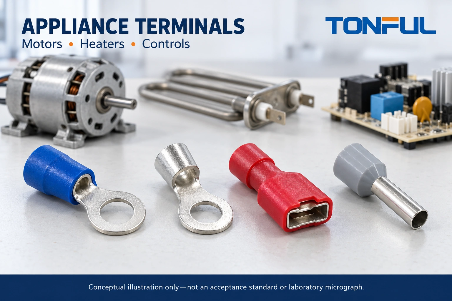
Appliance terminal selection starts at the connection point, not the color of an insulation sleeve. A motor lead, heater connection and control-board interface can share a conductor size yet need different contact geometry, insulation, retention and service procedures. Ordering one terminal for all three can move a problem from purchasing into assembly or field repair.
Use the appliance drawing and its approved component schedule as the starting authority. This guide helps engineering, procurement and harness teams create a selection record, compare candidates and decide what evidence is still missing. It does not authorize substitutions in a certified appliance or provide a universal terminal temperature or current limit.
Jump to: Circuit definition | Application matrix | Heat and routing | Tooling | Release record | Sourcing
Define the Circuit and Service Boundary
Record whether the terminal belongs to internal factory wiring, an external supply connection, a protective-earth path or a service-replaceable module. These roles affect the responsible specification and who may change the design. A terminal suitable inside one appliance enclosure is not automatically suitable as a field-wiring connector or exposed accessory.
Establish the Electrical Duty
Capture normal operating current, starting or cycling behavior, supply type and the fault-protection arrangement from the appliance design. Specify the actual wire construction, including conductor material, strand class and insulation diameter. An AWG or square-millimeter entry alone cannot describe every wire that will occupy the barrel.
For motors, distinguish the motor manufacturer’s interface from adjacent harness connections. For heaters, distinguish a remote control connection from a terminal immediately beside the heating element. For controls, distinguish switched power from sensor and communication circuits. These distinctions prevent an apparently convenient terminal family from becoming a default without review.
Keep Inspection Deenergized
Line-voltage appliance work belongs to qualified personnel under the applicable isolation and stored-energy procedure. Disconnecting a plug is not a complete procedure for every appliance: capacitors, multiple supplies, automatic operation and hot surfaces may remain hazardous. Establish and verify the safe condition before handling terminals. Never perform continuity or resistance measurements on an energized circuit, and do not improvise capacitor discharge methods.
Record the service boundary in the work instruction. If a replacement requires opening a guarded enclosure or altering a safety-related connection, route it through the appliance manufacturer’s authorized process rather than treating it as a general maintenance crimp.
Appliance Terminal Selection by Function
Choose the terminal architecture by the mating interface and its service needs. Ring terminals, blade receptacles and ferrules perform different jobs; they are not alternative shapes for the same connection. A ferrule prepares a conductor end for an accepting clamp. It does not replace a blade receptacle or independently provide a disconnect function.
| Appliance function | Interface information to obtain | Candidate decision | Release evidence |
|---|---|---|---|
| Motor harness | Motor terminal drawing, vibration exposure, lead exit | Approved receptacle, ring terminal or housing contact | Mating fit, lead support and assembled duty review |
| Heater assembly | Local terminal temperature, mating alloy and insulation arrangement | Heat-suitable construction selected from actual documents | End-product thermal evaluation and exact part identity |
| Control power | Board or relay tab width and thickness, clearances | Matching receptacle and insulating protection | Insertion, retention, polarity and enclosure checks |
| Control clamp | Clamp instructions, accepted conductor preparation | Bare conductor or specified ferrule preparation | Clamp compatibility and installed envelope |
| Protective earth | Appliance bonding design and approved hardware | Drawing-defined bonding termination | Separate bonding verification and traceable assembly record |
Distinguish Disconnects From Permanent Joints
A serviceable motor may need an approved removable interface, whereas a protected harness joint may be permanent. A removable terminal needs attention to mating cycles, latch or friction retention and access for correct removal. A permanent connection may simplify the interface but increase the amount of harness replaced during service.
Use TONFUL’s wire terminal manufacturing overview to identify candidate families for discussion, not as proof that a particular part fits the appliance. Ask for the exact model drawing and application instructions before adding it to the component schedule.
Review Heat Zones and Mechanical Loading
The appliance’s room-temperature environment is not the temperature at the connection. Heater radiation, motor losses, restricted airflow and neighboring components can change the local condition. Evaluate the terminal, sleeve, wire insulation and mating part together. Substituting a different sleeve material does not prove that the entire joint can tolerate the same exposure.

Avoid Material Shortcuts
Do not translate a color, a metal’s appearance or a generic material name into an operating rating. The terminal drawing must identify the construction; the application evidence must establish suitability. If an uninsulated terminal is proposed near a heater, the design still needs the required guarding, spacing, wire insulation and protection against accidental contact.
TONFUL’s non-insulated terminal category is a sourcing starting point for documented constructions. It is not a general high-temperature approval. Similarly, the nylon-insulated terminal category helps identify insulated candidates but cannot establish an appliance’s thermal envelope from the word nylon.
Inspect Loads Beyond the Barrel
Check whether cable routing bends the conductor at the barrel exit or pulls sideways on a blade receptacle. Confirm clearance to rotating parts, sharp edges and hot surfaces. Provide the support and slack required by the appliance design without allowing the harness to touch a heater or obstruct a fan.
Review assembly access with the covers, clips and adjacent parts in place. A connection that works on an open bench may become difficult to seat or inspect after installation. Include production orientation and the actual mating component in the sample review, rather than approving an isolated crimp coupon alone.
Match the Terminal, Wire and Tooling
A terminal is part of a termination process. Identify the terminal part number and revision, wire specification, preparation method, tool and cavity, and applicable crimp instruction. A tool that physically closes around a sleeve is not necessarily a suitable tool for the metal barrel beneath it.
Specify Preparation Without Inventing Limits
Take strip length, conductor brush, insulation position and crimp dimensions from the approved application specification. Verify that preparation leaves the intended strands intact and positions the conductor correctly. Do not trim strands to force a wire into an undersized barrel or put multiple conductors into a single-wire terminal without explicit approval.
For clamp-based control interfaces, review TONFUL’s cord end terminals only where the equipment instructions accept ferrules. Check sleeve length, collar envelope and the resulting crimp profile against the clamp opening and insertion depth. Ferrule color systems are not a substitute for reading the conductor-area marking and drawing.
Control Tool Changes
Use the TONFUL crimping tool range to frame a terminal-specific tooling inquiry. Ask which tool, die and adjustment instructions apply to the exact candidate. Keep evidence for tool identification, maintenance and setup verification with the assembly record.
Repeat the defined first-piece checks after relevant tool, material or setup changes. If the production method differs from the sample method, identify the difference before approval. A sample assembled with a laboratory tool does not automatically release an unreviewed production applicator.
Approve Samples Against a Release Record
Approve the installed connection, not merely a bag of terminals. The review should connect the intended use to the terminal identity, wire, mating component, process and inspection evidence. Separate checks that confirm dimensions from checks that evaluate the assembled appliance under its specified operating conditions.
UL explains that Recognized Components have conditions of acceptability, rather than automatically certifying the complete appliance. If recognition is claimed, verify the exact file, model and relevant conditions; do not infer approval from a logo in a catalog.

Build a Usable Approval Table
| Record field | Information to enter | Release question |
|---|---|---|
| Appliance and circuit | Model, revision, circuit reference and function | Is this the intended application? |
| Connection identity | Terminal, mating part and wire identifiers | Are all documents revision-matched? |
| Process identity | Tool, cavity, setup and operator authorization | Can production reproduce the sample? |
| Inspection basis | Drawing and application-specification clauses | Are criteria defined before inspection? |
| Evaluation evidence | Report references, conditions and sample identities | Does evidence cover the installed arrangement? |
| Exceptions | Open issue, owner and disposition | Is use blocked until resolution? |
| Authorization | Engineering and quality approval, date and scope | What exactly has been released? |
These are proposed record fields, not a report of testing performed. Define sample quantities, acceptance documents and required evaluations before ordering samples. Where destructive crimp checks or electrical testing are required, use the approved procedure and qualified facilities; do not substitute an informal hand pull for a specified test.
Resolve Differences Before Production
If a sample fits but the plating, insulation, wire source or mating interface differs from the proposal, record the mismatch. Engineering should decide whether it is acceptable, requires further evaluation or invalidates the sample. Purchasing should not close a discrepancy with a supplier email that lacks the responsible technical approval.
Keep rejected and superseded samples identified. A retained sample can help explain appearance and assembly intent, but its drawing and specification still govern measurable requirements. Document the effect of future substitutions on both the termination and the appliance approval basis.
Include the Assembly Sequence
Record whether the terminal is crimped before the harness enters the appliance, seated before a cover is fitted, or installed after a motor or heater module is mounted. The sequence determines tool access and which features remain visible for inspection. Ask production to demonstrate the proposed sequence with the intended routing clips and protective parts present. If a later step hides the conductor entry or mating engagement, define the inspection point before concealment. This review can reveal a need for a different approved terminal orientation or harness branch length without inventing new electrical limits or relying on an assembler to compensate informally.
Prepare a Controlled TONFUL Inquiry
Send TONFUL the motor, heater or control interface drawing, actual wire specification, local environmental conditions, service requirements and expected assembly method. Identify which data are firm requirements and which need a feasibility response. Include required documentation and the appliance approval constraints without assuming that every catalog part carries the same status.
Ask the response to distinguish an existing standard part from a modified or custom construction. Request candidate drawings, terminal-specific tooling information and a sample plan tied to your release record. Agree what changes require notification before production supply, including material, plating, insulation, tooling and manufacturing source changes.
For a useful next step, share the completed selection matrix with TONFUL and request a documented candidate review. Keep the order conditional on your engineering approval of the exact termination system and its use in the appliance, rather than on appearance, sleeve color or an unsupported claim of universal compatibility.