
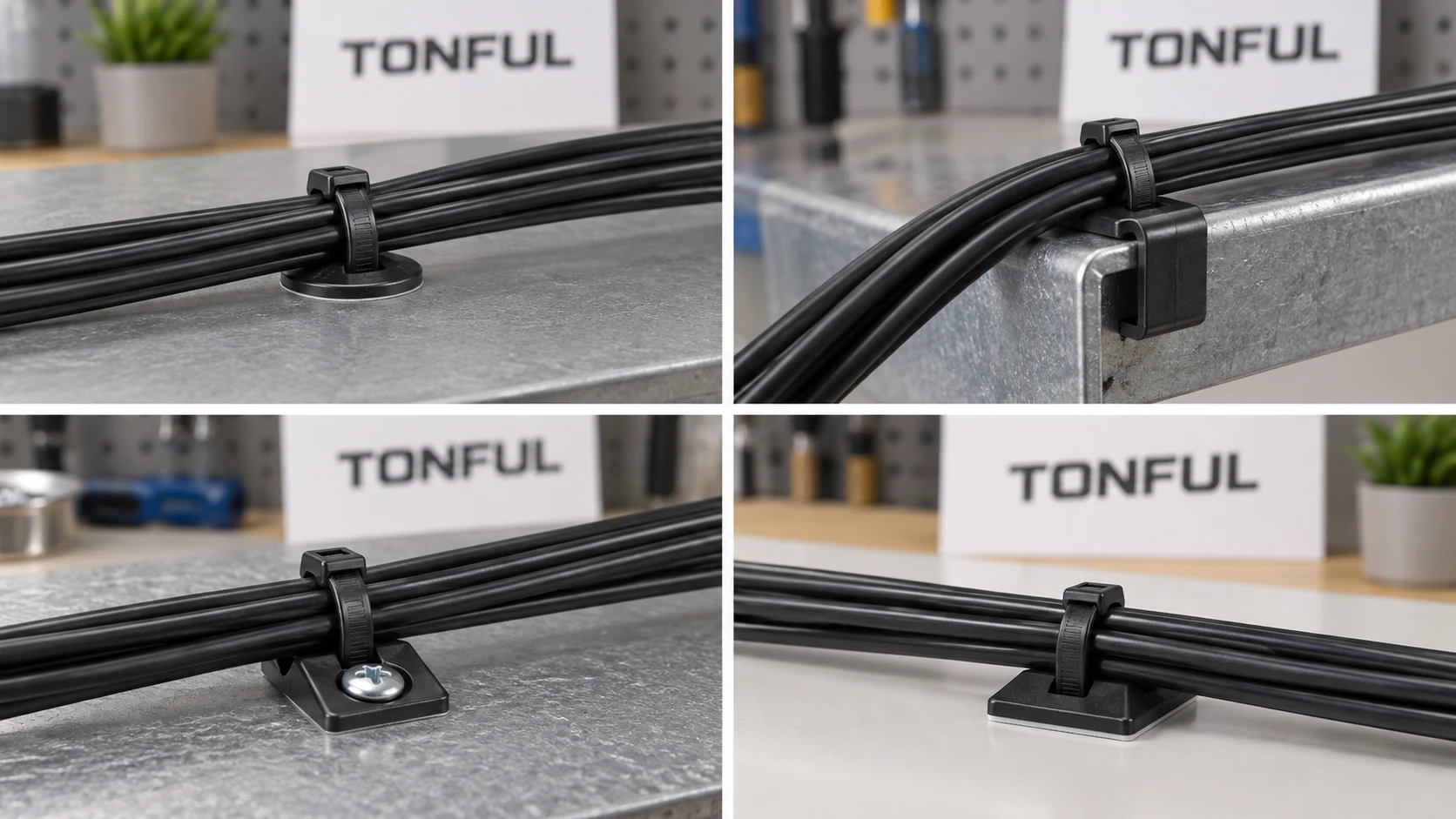
The tie loop is only one part of a cable-support assembly. A strong strap will not help if its fir-tree stem sits in the wrong hole, an edge clip slides off a flange, a screw base rotates, or an adhesive pad detaches from a dirty surface. Mount selection begins with the panel and the intended support function, not the tie length or loop tensile number alone.
This guide compares four common attachment methods across cabinets, vehicles, equipment and outdoor installations. It identifies the dimensions, installation controls and qualification evidence needed for each. It does not claim that any mount type is universally superior or that a catalog pull force applies to every surface.
Identify the Surface and Load Before the Mount
Draw the cable route and mark each intended support point. Record the bundle diameter, mass, stiffness and expected movement; clearance from heat, sharp edges and moving parts; connector strain; and whether the attachment merely positions wires or carries their weight. A wiring diagram rarely provides all mounting details, so link the decision to the mechanical drawing and the applicable installation requirements.
Inspect the actual substrate: sheet metal, painted flange, molded plastic, composite, glass or another surface. Note hole diameter and tolerance, panel thickness, coating, edge radius, fastener access, surface energy and contamination. An adhesive pad approved on clean painted steel cannot be assumed to bond to textured low-surface-energy plastic. A fir-tree stem approved for one panel stack may not seat in another.
The IEC 62275:2022 overview covers cable ties and associated fixing devices for managing or securing wiring systems in electrical installations. Its scope includes discussion of fixing-device test arrangements and adhesive types. It is a framework for evidence, not automatic approval of a selected mount for a vehicle, solar array or machine. Apply the customer drawing, code and authority requirements to the actual installation.
| Initial question | Why it matters | Record to obtain |
|---|---|---|
| Is there an approved hole? | Governs push-in or screw feasibility | Diameter, shape, tolerance, burr and thickness |
| Is there a suitable edge? | Governs clip grip and direction | Flange thickness, coating, lip and movement path |
| Is drilling or fastening allowed? | Prevents unauthorized panel changes | Approved hole, hardware and torque source |
| Is the surface bondable? | Governs adhesive-base feasibility | Substrate, cleaning, temperature and cure plan |
| What load must be held? | Separates bundling from support | Bundle weight, movement, direction and spacing |
| Can the point be inspected? | Controls service and replacement | Access, visible seating and inspection interval |
Fir-Tree and Push-In Mounts
A fir-tree mount uses flexible ribs to engage an approved hole. Some designs add a disc or offset saddle. Specify the required hole geometry, panel thickness including coating, backside clearance, insertion direction and expected retention. A round hole, oval hole, blind boss and threaded feature are not interchangeable without the exact product drawing. The TONFUL push-mount versus fir-tree guide discusses automotive examples; the same principle applies elsewhere: confirm the installed interface, not only the stem’s appearance.
Seat the stem fully with the approved tool or hand method. An unseated disc can conceal a burr, misalignment or hole-size mismatch. Inspection may need a visible flush condition, insertion-force window or accessible backside check. Where assembly is blind, define a reliable confirmation feature. Test extraction in the relevant directions after environmental conditioning, and inspect the panel hole for deformation when a service part is removed.
One-piece tie-and-mount designs reduce separate components but can make rework expensive if the stem or strap is damaged. A two-piece saddle may allow a different tie to be fitted while the base remains installed, but the permitted replacements must be specified. Do not reuse a damaged hole without an approved repair process.
Edge Clips
An edge clip grips an existing flange without a new hole. It can route a bundle alongside a panel and may help maintain clearance from the panel edge. The clip must match the flange’s thickness, radius, coating and insertion direction. Some product families allow an offset or different tie orientation; verify the actual candidate’s geometry rather than expecting the catalog image to match the production panel.
Measure both normal pull-off and sliding along the edge. A clip that grips tightly in a perpendicular pull may migrate under repeated longitudinal cable motion. Include minimum and maximum flange thickness and representative surface finishes. If a metal insert bites into paint, evaluate corrosion protection and the potential for scratches during installation or removal. The TONFUL edge-clip guide covers clip-specific choices in more depth.
For solar frames or vehicle flanges, confirm whether the equipment manufacturer permits attachment at that location. A clip can fit physically yet interfere with drainage, access, grounding hardware or a moving component. The solar and automotive edge-clip guide provides application context, but the release decision remains specific to the actual frame or panel.

Conceptual mounting comparison; check each hole, edge, fastener and adhesive surface against the selected part drawing.
Screw-Mounted Bases
A screw-mounted base relies on the base, fastener and substrate as one joint. Define hole or thread, screw grade and length, washer or locking feature, installation torque, panel stack and tool access. A base may rotate even if the screw remains installed, so verify the actual route direction and any anti-rotation feature. Excess torque may crack polymer or deform a thin panel; insufficient torque may allow loosening.
Decide whether the screw passes through a pre-approved hole or creates its own thread. Do not add holes to a vehicle structure, enclosure, PV module or safety-related assembly without design authorization. If the base is mounted to a plastic boss, include boss strength and environmental creep in qualification. If mounted outdoors, check water ingress and corrosion at the penetration as well as retention.
A screw base is often serviceable, but rework can strip a thread or change clamp load. Define replacement fasteners, allowable reuse and inspection after removal. Where a second tie is threaded through the base, its bundle range and loop strength are separate from the fastener joint. The final test should capture base movement and cable pressure, not merely screw torque.
Adhesive Bases
Adhesive mounting avoids drilling and may help route light bundles on a clean, approved surface. It introduces dependence on surface chemistry, cleanliness, texture, temperature, installation pressure and time before loading. The adhesive pad and plastic base may have different environmental limits. A mount that adheres in a short pull test can fail after thermal cycling, peel loading or fluid exposure.
The 3M VHB application guidance emphasizes surface preparation and substrate suitability for its own tape systems. It supports the general need to control bonding conditions, but it is not a specification for every adhesive cable-tie mount and does not establish TONFUL product performance. Follow the selected base’s approved adhesive instructions and validate the actual substrate, including coatings and cleaners.
Identify the load mode. Shear, peel and cleavage do not produce the same bond behavior, and a protruding cable bundle can create a lever arm. Define surface preparation, minimum application temperature, pressure, dwell or cure time before loading, and lot traceability for the pad. Test aged adhesion on production-intent panels. If an adhesive base is used as a temporary locator before another support is installed, state that explicitly; do not silently treat it as permanent primary support.
Adhesive failure needs careful diagnosis. If the pad detaches cleanly from the panel, review contamination or substrate compatibility. If adhesive remains on both sides but splits, review loading and aging. If the plastic base cracks while the pad holds, examine tool tension and base geometry. Preserve the failed interface for analysis instead of immediately scraping the panel clean.
Compare the Whole Assembly, Not Just Catalog Strength
The limiting interface may be the tie loop, head, mount, screw, adhesive bond, panel feature or cable jacket. A loop tensile value does not equal allowable installed working load or fixing retention. The TONFUL tensile-strength guide distinguishes tie-loop tests from application decisions. For a support function, also verify the exact fixing device and its declared or tested scope.
| Mount type | Critical interface | Typical evidence | Key failure to watch |
|---|---|---|---|
| Fir-tree | Stem and controlled hole | Hole gauge, insertion/extraction, panel condition | Partial seating or back-out |
| Edge clip | Clip and flange | Edge tolerance, pull-off and migration | Longitudinal sliding or paint damage |
| Screw base | Fastener, base and substrate | Torque, thread, vibration and rotation | Loosening or boss cracking |
| Adhesive base | Pad and prepared surface | Cleaning, dwell, aged peel/shear | Debonding or base fracture |
For each candidate, test the bundle at its minimum and maximum size and at the intended route orientation. Include cable jacket or conduit in the representative assembly. Where vibration or movement is relevant, watch for progressive displacement, fretting and connector strain during testing, not only the final pull-off result. No single catalog value substitutes for this installed-condition evidence.
Build a Verification and Inspection Record
Before testing, agree sample quantity, production lots, unaged references, sequential versus independent conditioning, destructive-test allocation and replacement rules. Define acceptance values from the customer drawing, product specification, installation code or approved qualification plan. Do not invent universal numbers for extraction, torque, bond strength or spacing. Retain raw results and the first failure mode.
| Record field | Required entry |
|---|---|
| Mount identity | Part, revision, material, adhesive or insert, lot |
| Substrate | Panel ID, thickness, finish, hole/edge geometry or surface |
| Installation | Operator, tool, setting, torque or surface-prep method |
| Bundle | Diameter, mass, jacket/conduit and route direction |
| Conditioning | Temperature, fluids, moisture, vibration and sequence |
| Result | Initial and aged retention, movement and cable damage |
| Decision | Acceptance document, deviation, approver and date |
Use the same critical features in production checks. A hole gauge, edge-thickness check, torque record or surface-cleaning verification may be needed depending on the method. Audit the actual installation position: a correctly manufactured mount placed beside a sharp edge may still cause failure. For field repairs, record what was removed and whether the panel feature or surface remains suitable for reuse.

Inspection should follow the load path from cable through tie and mount to the substrate.
Select With TONFUL
TONFUL’s cable tie range can be reviewed against the panel drawing and installation plan. Send the bundle size and mass, substrate material and finish, hole or edge dimensions, tool access, environment, support function and acceptance-source document. Ask for the candidate mount drawing and production-intent samples, then qualify the tie and attachment together.
Release only the tested combination of tie, mount, substrate and installation method. If the panel coating, hole, fastener, adhesive or cable route changes, reassess whether the original evidence still applies. A mounting change is not merely a purchasing substitution.