
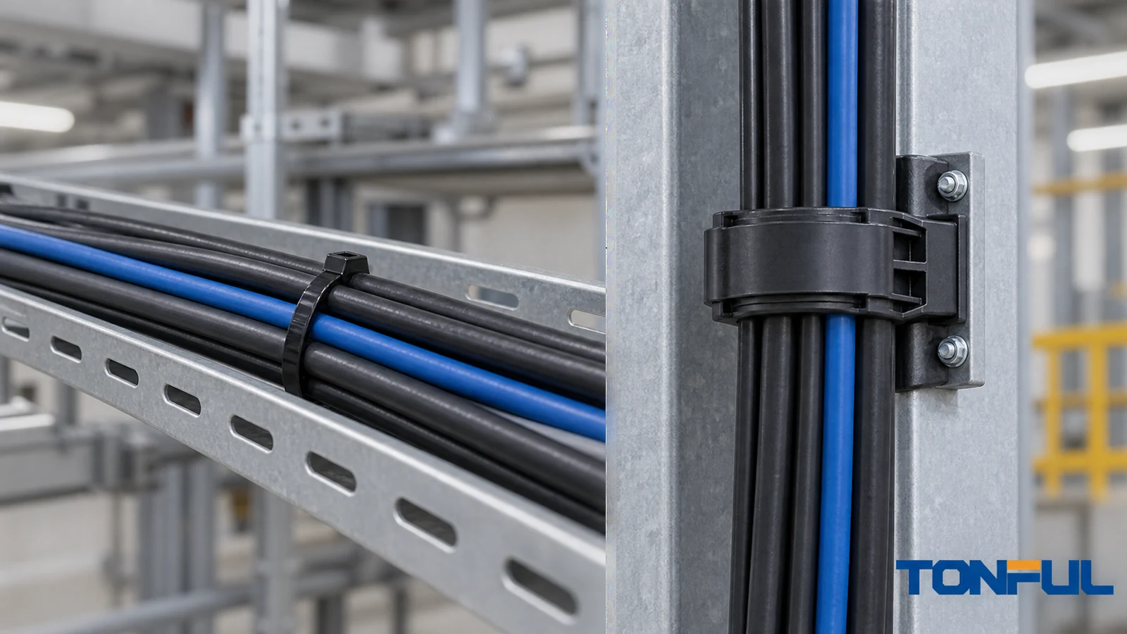
Short answer: A cable tie can keep electrical cables together or hold them along a route. It should not automatically be treated as the component that carries their weight. Primary support requires an appropriate, verified tie-and-fixing arrangement, a suitable fastener and substrate, and an installation permitted by the applicable electrical rules and equipment instructions. A high loop-tensile number alone does not establish that the installed assembly can support a cable over time.
This distinction matters in cabinets, overhead runs, vertical drops and outdoor wiring. The same tie may be a harmless routing aid on a properly supported tray but an unverified load-bearing component when it is the only thing preventing a cable from sagging. Before selecting a tie, trace where the cable weight actually goes.
Securing and Supporting Are Different Jobs
Bundling gathers individual wires into a manageable group. Securing restricts movement or maintains routing relative to another surface. Supporting carries all or part of the cable’s weight. The difference is not the appearance of the installation; it is the load path. If the tie were removed, would the cable remain adequately supported by a tray, cleat, hanger or other approved device? If not, the tie may be performing a support function.
| Installation example | What carries the cable weight? | Typical tie role | Decision point |
|---|---|---|---|
| Horizontal tray with cables resting on its base | Tray and its hangers | Organizes or restrains cable | Check tie tension and tray instructions. |
| Cabinet wiring clipped beside a supported duct | Duct, designated supports or terminals as designed | Routing or local restraint | Do not let terminals become accidental strain relief. |
| Vertical cable bundle hung from a wall point | Tie, fixing, fastener and wall may carry weight | Potential primary support | Verify complete assembly and permitted application. |
| Overhead span with no independent support | Tie or fixture may carry the span | Primary support if it prevents sagging | Do not substitute an ordinary tie for an engineered support. |
| Cable at a connector or enclosure entry | Approved gland, clamp or other strain relief should take the load | Secondary organization | A nearby tie does not automatically protect the termination. |
In a mixed installation, one tie can both restrain and support. Treat the more demanding function as controlling. A drawing that simply says “cable tie” does not establish its intended role.
What UL and IEC Information Actually Establishes
UL Solutions’ cable-management guidance distinguishes a tie used to secure wiring from a tie used to provide primary support. In UL’s described product categories, ties and fixing devices investigated for primary support can carry the S suffix, including Type 2S and Type 21S. That designation is not a general permission to suspend every cable in every location. Check the exact product’s certification record, marked use, specified accessory or fixing device, and installation conditions. The wiring method and the applicable electrical code still control whether that form of support is permitted.
IEC 62275:2022 addresses cable ties and associated fixing devices used to manage and secure electrical wiring systems and describes additional considerations for supporting applications. Do not assume an IEC reference automatically conveys a UL support classification, or the reverse. Certification schemes, national deviations, product constructions and installation permissions may differ.
The standard number on a catalog page is therefore only a research starting point. Ask for the exact SKU, certification file or listing, current datasheet, authorized tie-to-mount combination, installation instructions and any restrictions on cable type, position, temperature or location. The TONFUL cable ties range is a place to start a product inquiry, not proof that every listed tie is support-rated. Do not publish or purchase on an assumed certification claim.
Why Loop Tensile Strength Is Not a Working Load
Minimum loop tensile strength describes a defined test on a closed tie. It is useful for comparing certain tie constructions under stated conditions, but it does not by itself establish a permissible continuously suspended cable mass. UL explicitly distinguishes the tie’s loop-tensile characteristic from the fixing device’s mechanical strength. A support assembly may also be limited by the anchor, screw, adhesive, substrate, temperature exposure or cable jacket.
Consider a tie advertised with a large tensile figure. A wall mount may detach before the tie breaks. A thin enclosure panel may deform. A tie may creep under sustained load at elevated temperature. At an edge, the cable jacket could be damaged even though the tie remains intact. These are different failure modes and require different evidence. See the TONFUL cable-tie tensile-strength guide for the test-property distinction, then return to the actual installed assembly before deciding support suitability.
Do not divide loop-tensile value by cable mass to invent a safe tie count. Obtain the project-approved load method and distinguish tie, fixing and assembly ratings.
Trace the Complete Load Path
For a proposed support point, follow the path from cable and contents → tie loop → tie head or integral mount → separate fixing device → fastener → substrate. The weakest or unverified interface is the problem to solve. Check both immediate strength and the conditions expected throughout service. An adhesive pad intended for routing may not be a suitable permanent overhead support, and a metal screw does not validate a plastic fixing device attached to it.
The following conceptual diagram shows the load-path elements, not an approved installation or acceptance limit.

Cable and Route
Record cable type, quantity, outside diameter, total mass per unit length and route orientation. Include foreseeable additions, service loops and movement allowances. Avoid creating an unsupported free span just because a bundle looks light by hand. The project drawing, wiring method and equipment instructions determine allowable support spacing; this article provides no universal spacing value. A tie should not force a cable below its specified bend radius, pinch it against a sharp edge or transfer load into a connector.
Tie and Fixing Device
Match the tie width, length, head style, material and service environment to a specific fixing device or integral mount. Check the stated compatibility rather than relying on a strap that happens to fit through a slot. Where the manufacturer requires a tool or tension setting, use that process and inspect for jacket indentation or head damage. The TONFUL guide to choosing tie size helps define bundle geometry, but geometry alone does not approve a support point.
Fastener and Substrate
Confirm mounting-hole size, screw or anchor specification, installation torque, substrate thickness and condition, and corrosion protection. Ask who approved the anchor in concrete, sheet metal or a composite panel. A fixing device can have a legitimate laboratory rating while the actual wall or panel connection remains unverified. Where the substrate is unknown, stop and obtain an engineered fastening detail rather than making a field substitution.
Environment and Service Life
Check maximum and minimum operating temperature, UV exposure, humidity, chemicals, vibration, cyclic loading and required service life. A one-time pull check cannot replace aging or sustained-load evidence. For outdoor routes, specify material and exposure evidence; color alone is not a qualification. For high-vibration equipment, assess abrasion, tie-head orientation and whether a cable can move against a bracket. Include inspection access and replacement method in the design.
Choose the Right Support Strategy
| Need | Prefer to evaluate | Why an ordinary tie may not be enough |
|---|---|---|
| Carry a long horizontal cable route | Suitable tray, ladder, raceway or approved hangers | Bundle organization does not establish support spacing or loading. |
| Hold a vertical drop | Listed or specified clamp, cleat or qualified tie-and-fixing system | Long-term gravity load acts on every interface. |
| Protect a termination from pull | Correct gland, strain relief or clamp | A tie near the connector may move or shift the load. |
| Control a short cabinet branch | Approved duct, clip or local restraint | Routing and jacket protection are still required. |
| Keep cables apart in a tray | Appropriate ties or separators | Restraint must not crush jackets or violate tray instructions. |
These are selection directions, not universal substitutions. A cable cleat may need its own fault-duty evaluation; follow the code, equipment documentation and project specification.
A Field Checklist for Approval
The following record helps purchasing, engineering and installation teams avoid a vague “heavy-duty tie” approval. Leave unknown entries open; do not mark them conforming because a sample looked strong.
| Check field | Required evidence or entry | Result |
|---|---|---|
| Intended role | Bundling, securing, partial support or primary support | Pending / Accepted / Rejected |
| Cable and wiring method | Cable construction, quantity, mass, route and applicable rules | Pending / Accepted / Rejected |
| Exact tie identification | Manufacturer, SKU, material, lot and revision | Pending / Accepted / Rejected |
| Support qualification | Product-specific certification or test evidence and permitted scope | Pending / Accepted / Rejected |
| Fixing device | Exact compatible mount or integral fixing and mechanical-strength evidence | Pending / Accepted / Rejected |
| Fastener and substrate | Specified anchor, mounting detail and approved surface | Pending / Accepted / Rejected |
| Installation conditions | Tool, tension, orientation, spacing and bend protection | Pending / Accepted / Rejected |
| Environment | Temperature, UV, chemical, moisture and vibration requirements | Pending / Accepted / Rejected |
| Verification | Sample installation, inspection, design approval and change control | Pending / Accepted / Rejected |
For a critical point, record drawing revision, inspector, date and location. Photograph the whole load path. Assess representative cable, mount, fastener and substrate under the approved plan. Reverify a changed anchor or panel thickness.
Installation and Maintenance Controls
Before work, isolate circuits where required and follow the equipment’s installation procedure. Support the cable temporarily while positioning the permanent fixing. Do not use the cable as a handle, and do not pull a tie tight enough to flatten insulation, impair shielding or create a bend at a connector. Remove tails flush with an appropriate tool; a sharp cut can injure installers or abrade neighboring jackets. For alternative tie constructions and their installation implications, see the TONFUL cable-tie types guide.
After installation, inspect the mounted assembly under its actual cable weight. Look for mount rotation, anchor movement, tie creep, jacket indentation and unacceptable sag. Verify that access panels can be opened without shifting the load. Record any nonconformance against the approved drawing rather than tightening more ties as an undocumented field fix.
Periodic inspection should look for brittle straps, loose fixings, corrosion, added cables and insulation wear. Replace damaged parts with the approved SKU. Repeated failure calls for a load-path investigation, not just a higher tensile figure.

Questions for a Cable-Tie Supplier
When asking for a proposal, state whether the tie is only for routing or must carry primary cable weight. Provide the wiring method, cable mass, route orientation, environmental profile, service life, fixing surface and required approval documents. Ask for the exact model’s declared values and certification scope, not a family-wide brochure statement. If a fixing device is separate, ask which combinations were evaluated and whether substitute screws, anchors or adhesives are allowed.
Ask how production controls material, dimensions, head engagement, fixing-device construction and traceability. A successful sample does not release every lot or substrate. The TONFUL cable-ties buying guide can structure the wider RFQ.
Work With TONFUL
TONFUL can discuss cable-tie selection against your routing or support requirement. Send the cable and installation drawings, the specific location, expected load path, environment and any mandated certification or test plan. Ask for a written response identifying the exact product and evidence available. If primary support is needed, do not treat a generic cable-tie catalog entry or loop-tensile value as approval. Release the application only after the tie, fixing, fastener, substrate and installation method are verified together under the governing project requirements.
Technical Sources
- UL Solutions, Cable Ties for Cable Management: distinction between securing and primary support, product categories, and tie/fixing characteristics.
- IEC 62275:2022, Cable management systems—Cable ties for electrical installations: standard scope and support-related context. Apply the purchased edition and national requirements to the exact project.