
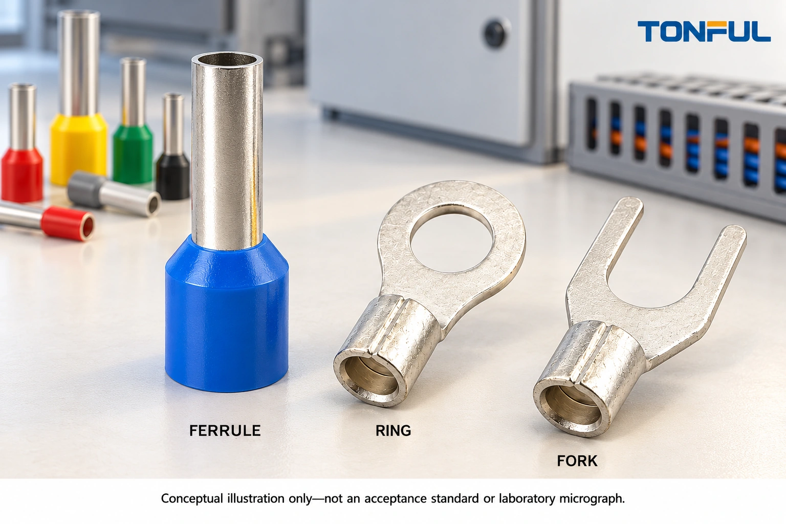
Control panel wire termination begins at the receiving device. A ferrule belongs in a connection designed to accept its finished sleeve. A ring belongs on compatible stud or screw hardware. A fork is appropriate only where the equipment and project requirements permit its open tongue. None is a universal upgrade over the others.
For a panel builder, the practical task is to turn those differences into a controlled termination schedule. That schedule connects each wire to a receiving point, approved end treatment, tool setup and inspection requirement. It prevents technicians from making undocumented choices at the bench.
This guide provides a selection matrix and release record for that process. It does not replace equipment instructions, the applicable panel standard or project engineering approval. Work must be performed with energy sources isolated and the safe condition verified by qualified personnel under the applicable procedure, including stored energy and possible backfeeds.
Jump to: Start at the device, Choose the end, Build the schedule, Prepare and assemble, Inspect and release, Manage changes.
Start Control Panel Wire Termination at the Device
Read the receiving-connection instructions
Identify the exact terminal block, relay socket, contactor, drive, power supply or distribution component. Obtain its permitted conductor types and cross-sections, strip length, end-treatment limitations and installation method. A screw visible on the top does not prove that a ring or fork is intended; the screw may actuate a pressure plate for direct wire entry.
Separate conductor ranges with and without ferrules where the documentation does. The sleeve and formed profile change the termination’s external dimensions. Do not assume a block’s largest bare-wire size remains its largest ferruled-wire size, or that a profile accepted in one device fits another.
A manufacturer’s approval can apply to a particular combination rather than a generic product name. For example, the official Phoenix Contact ferrule overview discusses ferrules and selected tooling combinations. It does not establish universal compatibility of every ferrule with every receiving device, or transfer that manufacturer’s approvals to TONFUL parts.
Capture physical access and service conditions
Check available wire-entry depth, adjacent barriers, collar clearance and room to use the prescribed tool. For screw or stud hardware, check tongue width, hole size and space for insulation and covers. A technically correct conductor size can still produce a termination that cannot seat flat or be inspected.
Include wire routing and service access in the review. The completed connection should not carry the weight of an unsupported cable or be twisted by a tight bend immediately at the barrel. A termination selected without routing space may create avoidable strain even when the crimp itself is acceptable.
The TONFUL terminal manufacturing range provides starting product families. The final choice remains tied to the actual receiving hardware and controlled panel design, not a broad category description.
Choose Ferrules, Rings or Forks by Interface
Ferrules manage strands at compatible clamp entries
A ferrule encloses stripped conductor strands in a metal sleeve. Choose its conductor capacity, sleeve length and formed profile to suit the wire and receiving device. The plastic collar assists entry and strand management; it is not the conductive clamping region or a substitute environmental seal.
Review cord-end terminal options against the clamp’s permitted end treatments. Some receiving designs accept suitably prepared stranded wire without ferrules. Others have specific insertion or actuation instructions. Do not declare ferrules mandatory for every spring connection or every screw connection without the applicable requirement.
Twin ferrules require separate approval. Their purpose is not permission to double up any connection. Confirm permitted conductor count, wire combination, ferrule capacity and receiving-device compatibility. Do not remove strands, fold wire or fit two sleeves into one opening to avoid an engineering review.
Rings and forks depend on mounting hardware
A ring has a closed tongue around compatible hardware and normally requires the relevant hardware to be removed for installation or removal. A fork has an open tongue that may allow removal after loosening. That maintenance convenience does not override restrictions on terminal type, retention or use at a particular circuit point.
For either form, select conductor barrel and mounting dimensions independently. A hole that fits the screw says nothing about barrel fit on the wire. Check tongue seating, sleeve clearance, hardware stack and any device-specified washer arrangement. Do not use an oversized hole to compensate for a missing part.
| Receiving interface | Candidate end treatment | Confirm before release | Do not assume |
|---|---|---|---|
| Approved clamp entry | Ferrule or permitted prepared wire | Wire range, sleeve length, profile and insertion method | Ferrule always required |
| Stud or removable screw point | Ring terminal | Hole, tongue, hardware and tightening instruction | Any ring fits any stud location |
| Approved screw connection | Fork terminal | Fork permission, retention and seating | Faster removal means universal suitability |
| Two-wire connection | Approved twin ferrule or specified alternative | Conductor count and exact combination | Nominal opening size authorizes two wires |
| Device-specific connector | Specified contact system | Part, housing and tooling instructions | Ring, fork or ferrule can substitute |
Use the nylon-insulated terminal category when the schedule calls for insulated rings or forks. Use the non-insulated category only with the intended insulation, spacing and guarding strategy. A sleeve does not establish a completed panel’s voltage rating.

Build a Controlled Termination Schedule
Give every connection an executable instruction
The schedule should translate drawings into repeatable work. Use a connection identifier that matches wire markers and the schematic. Include receiving-device identity, conductor construction, approved terminal part and the document that supplies the installation criteria. Avoid instructions such as use suitable ferrule or tighten securely.
| Schedule field | Entry required | Purpose |
|---|---|---|
| Connection ID | Device and terminal designation | Links assembly to schematic |
| Wire | Size, material, strand construction and insulation | Controls barrel and support compatibility |
| Receiving point | Device part number and revision | Fixes permitted preparation method |
| End treatment | Terminal part or explicitly permitted bare-wire preparation | Prevents bench substitutions |
| Tooling | Tool, die, cavity and locator as applicable | Makes crimp setup reproducible |
| Installation source | Strip, insertion and tightening instructions | Prevents improvised limits |
| Verification | Required visual, dimensional and functional checks | Defines release evidence |
| Traceability | Material lot, operator and inspection record | Supports containment and change review |
Where torque applies, copy the value and units from the approved equipment instruction into the controlled work documentation. Do not use a single shop-wide torque for different devices, and do not infer torque from screw diameter alone. Define the relevant tool and verification method under the panel builder’s quality system.
Resolve exceptions before assembly
Flag uncertain end treatments, double-wire requests and unavailable part numbers for engineering disposition. An approved alternative should be recorded with its limits, not passed informally between shifts. Purchasing substitutions need the same interface review as the original selection.
Identify protective-conductor and other safety-related connections explicitly so their verification cannot disappear inside general continuity checks. Their design and acceptance requirements come from the applicable equipment and panel standards. This article does not authorize a different termination merely because it fits mechanically.
Control Preparation, Crimping and Installation
Make the wire preparation match the termination
Cut and strip according to the released instruction. Inspect for damaged strands, insulation cuts and conductor contamination. Match stripped length to the chosen barrel or sleeve and its insertion requirements. Do not hide excess bare conductor with an improvised covering or trim visible strands after crimping to disguise incomplete insertion.
Use the identified crimping-tool system with the approved die, cavity and positioning features. Ferrule tooling forms the metal sleeve, not the plastic collar. Ring and fork tooling must suit the actual barrel construction and insulation system; their outline does not determine the die.
Perform the prescribed first-piece checks after relevant material or tooling changes. If destructive verification is required, use the approved sample plan, fixtures, test conditions and acceptance source. Do not return tested specimens to the panel or treat a continuity indication as proof of crimp strength.
Install without changing the approved interface
Insert the termination fully using the device’s method. For clamp entries, ensure the conductive sleeve reaches the intended clamping region without the collar blocking engagement. For rings and forks, confirm flat seating and the correct hardware arrangement before tightening as instructed.
Route and support the wire so the termination is not forced sideways. Restore barriers, covers and wire-duct management without trapping insulation or obstructing service access. Do not add solder to a crimp or tin strands to solve a loose fit unless the explicitly approved process requires that treatment.
Inspect the Completed Panel Connections
Inspect both workmanship and design conformity
Check wire identity, terminal identity, complete insertion, exposed conductor, insulation condition, mounting fit and routing. Compare against the schedule and receiving-device instructions. A neat panel can still contain a wrong terminal, an unapproved twin connection or a ferrule too short for the clamp.
Use a structured record for deviations rather than marking every connection acceptable from appearance alone. Hold the affected circuit or assembly, identify the scope since the last verified condition, and obtain an authorized repair instruction. A repaired termination requires the specified reinspection and any affected functional checks.
| Inspection record | Information to capture |
|---|---|
| Identity | Connection ID, wire and end-treatment part |
| Installation | Receiving point and instruction revision |
| Observations | Insertion, insulation, seating, routing and guarding |
| Required verification | Applicable tightening, continuity or other test record |
| Nonconformity | Description, containment and authorized disposition |
| Release | Inspector, date and evidence reference |

Keep testing within the approved panel procedure
Continuity, protective-bonding, insulation or other tests must follow the applicable procedure, including isolation of sensitive devices where required. Do not apply a generic test voltage or current to connected electronics. De-energized workmanship inspection does not authorize later energized diagnostics by unqualified personnel.
A torque witness mark can be a process aid if the quality plan uses it, but it is not independent proof that the correct torque was applied. Retain the required installation and verification evidence rather than relying on paint marks alone.
Manage Service Changes and Sourcing
Preserve the approved connection after handover
Service instructions should identify replacement terminals and tooling, permitted wire changes and required reinspection. If a technician changes a device, review its connection instructions before reusing the old end treatment. Similar function does not guarantee identical clamp capacity or installation requirements.
Update the termination schedule and as-built documentation after an authorized change. Keep superseded part identities available for traceability while preventing them from being issued as current instructions. Review repeated repair findings for a design or process correction rather than accepting the same exception indefinitely.
Send TONFUL the wire construction, receiving-interface details, desired ferrule or tongue dimensions, insulation needs and approved inspection requirements when requesting samples or a quotation. Ask for exact part drawings and matching tooling information. A connection-point-based request gives both teams a clearer sourcing decision than a list containing only wire sizes and terminal colors.