
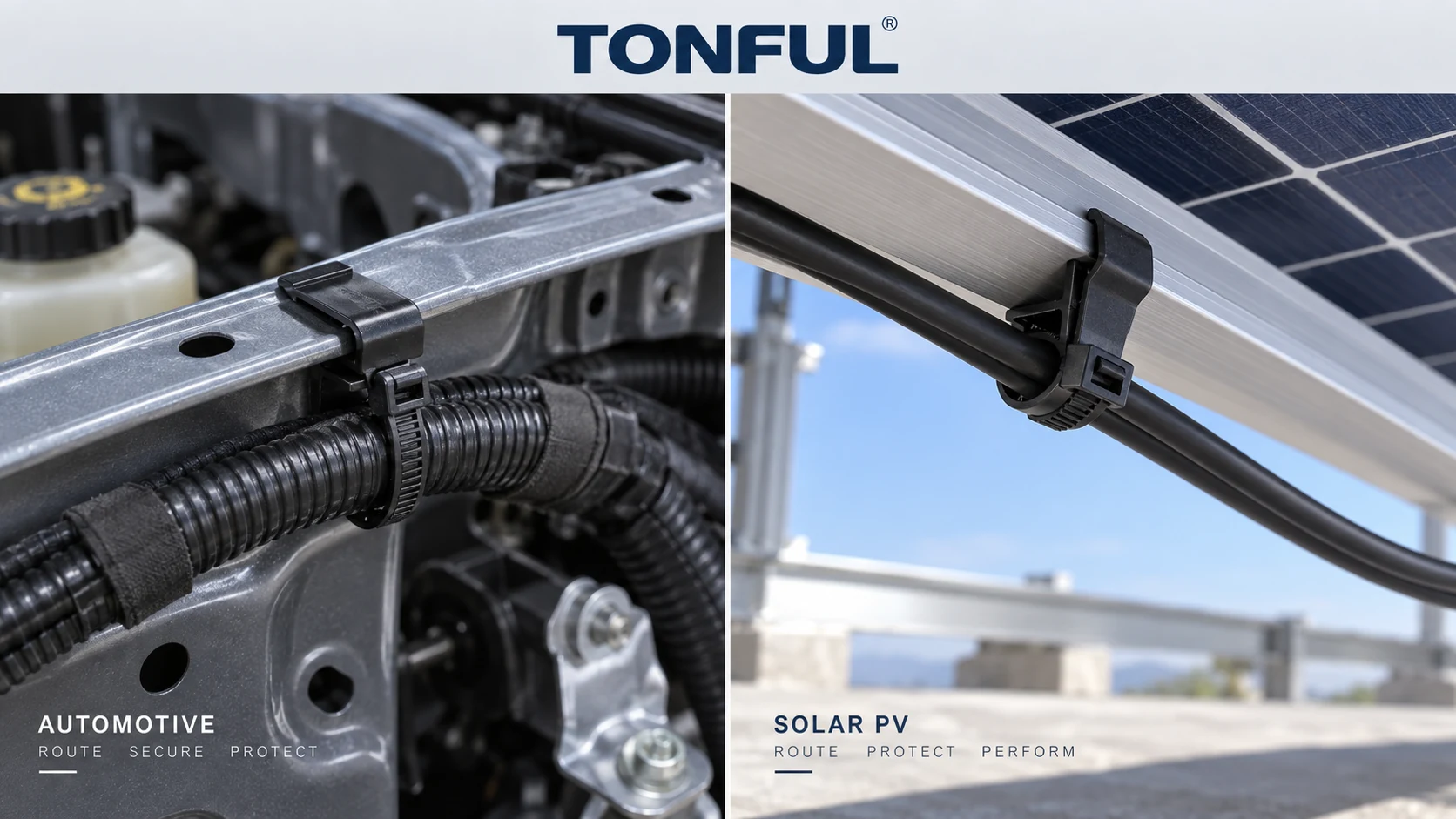
An edge clip lets a cable tie attach to a panel flange without drilling a new hole. That convenience does not make every flange a safe fixing point. The clip must match the edge thickness and finish; the tie must fit the bundle; and the complete route must keep cables away from abrasion, heat, moving parts or unsupported tension. The same style of clip may serve a vehicle harness or a solar array, but those installations demand different evidence.
This rewrite replaces unsupported universal installation times, force values, service-life estimates and support spacing with a project-specific decision method. Use the exact clip drawing, vehicle or module instructions, cable specification and approved qualification plan before release. No TONFUL part is claimed certified or validated for a particular vehicle or PV frame by this article alone.
What the Edge Clip Actually Holds
An edge-clip assembly can be a one-piece tie with an integrated fixing feature or a two-piece combination of clip and replaceable tie. Some designs use a metal spring insert; others use different retention constructions. Do not assume that every clip contains the same steel, polymer or spring geometry. Identify the controlled part number, drawing revision, material, band orientation and approved edge-thickness range for the candidate.
The clip grips the flange. The tie holds the bundle. The panel or frame supports both. A strong tie loop cannot compensate for a clip that slides along an edge or a panel coating that is damaged by insertion. Record whether the assembly merely positions a cable, provides support, or maintains a required clearance. Those functions may have different acceptance rules.
The HellermannTyton automotive catalogue illustrates product-specific edge-clip variants and panel-thickness ranges. Its dimensions apply to the identified HellermannTyton designs, not to TONFUL products or a universal edge-clip class. Use such documentation as an example of the detail to request from any supplier, not as a substitute for the selected part drawing.
| Interface | Define on the drawing | Verify on the installed sample |
|---|---|---|
| Flange | Material, nominal and tolerance thickness, coating, lip radius | Seating, paint damage, pull-off and edge migration |
| Clip | Insert, housing, insertion direction and orientation | Retention after exposure and removal condition |
| Tie | Length, width, serration, head and tool method | Bundle pressure, slip, tail and jacket damage |
| Cable | Diameter, jacket, weight and movement | Bend radius, abrasion, slack and connector strain |
| System | Adjacent heat, water, moving parts and access | Routing clearance and inspection reach |
The TONFUL edge-clip design guide covers basic construction. This page goes further by comparing the very different vehicle and PV release boundaries.
Automotive Harness Applications
On a vehicle, a clip may attach a harness to a body flange where drilling is prohibited or a push-in hole is not available. The route can be inside a door, under a body panel, near an engine compartment or on heavy equipment. Each location changes temperature, fluid exposure, vibration, service access and the consequence of a loose harness. Do not describe one clip as suitable for all of them without the applicable drawing and validation.
Start with vehicle and harness identity: model, production version, flange location, cable branch, connector position and the applicable customer specification. Measure the real edge thickness across tolerance and coating conditions. Check the installation direction and whether the clip can seat fully with the harness already in place. A narrow opening may allow insertion but prevent later inspection or removal.
Vibration must be evaluated on the installed route. Normal pull-off from a laboratory coupon is not enough if the harness pulls longitudinally, rotates around the flange or rubs against a nearby bracket. Monitor clip migration, tie looseness, conduit wear, connector strain and noise during the project-approved profile. Retest retention after environmental conditioning if required. A failed tie can be secondary to a moving clip or a stiff harness branch.
In a service area, define whether the clip may be removed and reused. Removal can deform a spring insert or scratch coating. A two-piece clip may allow replacement of the tie while keeping the clip, but that is not a blanket rule; it depends on the product and inspection procedure. The TONFUL push-mount versus fir-tree guide helps compare an approved hole-based alternative when the flange proves unsuitable.
Solar DC Cable Applications
Under a PV array, cable-management hardware has to prevent sagging, abrasion, connector tension and contact with hot or sharp surfaces. Exposure varies around module edges, gaps, rails and roof transitions; an underside location is not automatically protected from UV, heat or moisture. The U.S. Department of Energy’s PV cable-management guidance discusses premature failure of ordinary plastic ties under combined exposure and the need for durable routing and support. It does not approve a specific TONFUL edge clip or set one universal spacing rule.
Before clipping to a module frame, confirm the module and racking manufacturer’s permitted attachment areas. A clip that fits an aluminum edge can still block drainage, interfere with mounting hardware, contact a cable jacket at a sharp radius or violate the equipment instructions. Record frame profile, thickness, coating or anodizing, orientation and edge clearance. Verify whether the candidate clip and tie are intended to secure or support DC wiring under the applicable installation requirements.
Cable and connector instructions determine bend radius, strain relief and routing. Do not suspend a connector from a tight tie or create a low point where water and debris collect. Maintain inspection access. A metal clip or insert requires attention to corrosion, galvanic contact and sharp edges. A polymer tie requires exact-product evidence for temperature, UV and chemical exposure. The TONFUL solar polymer comparison provides material context, but resin selection alone does not validate a complete clip-on-frame assembly.

Conceptual routing comparison only; the approved vehicle flange and PV frame locations must come from their respective controlled documents.
Qualified personnel should manage energized PV work under the site’s electrical safety procedures. Do not pull a live conductor to test clip grip. For retrofit work, inspect cable jackets and connectors before disturbing existing supports, photograph the route, and define how removed fragments will be collected. Replacing one failed tie with the same unidentified material is not a root-cause correction.
Two Applications, Different Approval Questions
| Question | Automotive release | Solar/PV release |
|---|---|---|
| Approved mounting feature | Vehicle body or equipment drawing | Module/racking instructions and site design |
| Dominant movement | Road/engine vibration, door cycles, service | Wind, thermal expansion, maintenance |
| Environment | Fluids, road salt, heat, moisture by location | UV, roof heat, water, dust, coastal deposits |
| Critical clearance | Moving and hot parts, body edges, connectors | Frame/rail edges, roof surface, connectors |
| Evidence | Vehicle-specific harness validation and control plan | PV cable-management plan, equipment instructions and site checks |
| Maintenance | Service access and clip removal rule | O&M inspection and safe retrofit procedure |
Neither column is a universal checklist of numeric limits. The customer, equipment manufacturer or authority defines the applicable conditions and acceptance values. A clip used successfully in one vehicle does not prove outdoor PV suitability. Likewise, a solar-rated material does not establish vibration retention in a vehicle door.
The UL cable-tie application guidance distinguishes securing from certain support uses and emphasizes exact product markings and compatible fixing devices. A claimed UV rating, support Type or certification must be checked for the precise model and installation. Do not infer a project’s code compliance from the words “edge clip” or from a supplier’s general catalogue.
Installation Method and Common Errors
Inspect the flange first. Burrs, paint buildup, deformation or corrosion can stop full seating or change retention. Insert the clip in the documented direction without striking nearby wires. Confirm the intended seated condition and tie orientation. Route the bundle with adequate slack and clearance, then tighten using the approved tool setting. Cut the tail flush and examine cable pressure and insulation.
Common errors include forcing a clip beyond its panel range, treating a coated thickness as bare-metal thickness, mounting on an unapproved frame lip, aiming a metal edge toward the jacket, tightening around a connector boot, and allowing the tie to carry load that should be supported by another device. A nominally identical edge clip can have a different orientation or retention profile; confirm its part number rather than selecting by color.
If installation is blind, define a seating cue that the operator can confirm. If inspection requires a mirror or camera, include that in the work instruction. A visual check from only one side may miss a partially engaged spring. After installation, follow the harness route to the next support point and confirm there is no new abrasion or tension path.
Qualify the Installed Assembly
Use production-intent clips, ties, panels or frames and cables. Define sample quantity, lots, unaged references, independent or sequential conditioning, destructive-test allocation and replacement rules. Test minimum and maximum flange dimensions and bundle sizes. The agreed plan may include insertion, pull-off in relevant directions, sliding resistance, temperature, moisture, corrosion, UV and vibration as applicable. Report failure location rather than only a pass/fail label.
| Record field | Required entry |
|---|---|
| Part identity | Clip/tie number, revision, material, lot and supplier |
| Mount | Vehicle flange or PV frame ID, thickness, finish and edge profile |
| Cable | Type, diameter, weight, bend radius and connector location |
| Installation | Direction, tool, tension setting, operator and visual cue |
| Conditioning | Method, severity source, sequence and sample allocation |
| Result | Initial/aged retention, migration, abrasion and first failure |
| Release | Acceptance-source document, approved scope, reviewer and date |
Keep specific results for both components of a two-piece assembly. A tie can pass loop tensile testing while the clip backs off the edge. A clip can retain well while the cable jacket is damaged by tension. The TONFUL cable-tie tensile guide explains why a loop rating is not an installed support rating.

Inspection should follow the complete load path from cable through tie and clip to the frame or flange.
Diagnose and Prevent Field Failures
Preserve the failed assembly and document the exact mounting location before moving cables. If the clip migrated, check edge shape, load direction, coating and vibration. If it pulled off, compare flange thickness and insertion condition with the approved drawing. If the strap fractured, examine material condition, tension and sharp edges. If cable insulation is damaged while clip retention remains good, investigate contact pressure, bend and movement rather than replacing only the clip.
For PV arrays, map failures by exposure, frame position and installation crew. For vehicles, map them by assembly station, body revision and service history. Compare failed and retained samples and verify changes to material, tooling, flange coating or cable route. Update the drawing, qualification evidence and inspection plan before a broad substitution. Do not use a universal “expected life” to overrule a local failure investigation.
Work With TONFUL
TONFUL’s cable tie range can be reviewed for a vehicle or PV project. Provide the flange or frame drawing, cable route, bundle size and mass, exposure profile, installation tool, support function, required markings and test plan. Request the controlled drawing and production-intent sample for the proposed edge-clip assembly. Release only the exact combination that has the required evidence.