
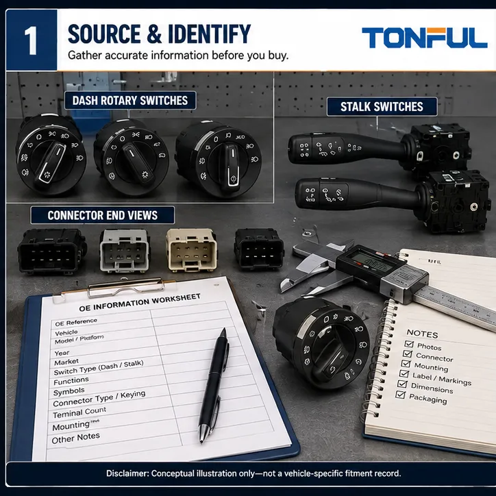
This guide helps distributors, fleet buyers, repair businesses, and procurement teams identify what a headlight switch does, verify its application, and avoid ordering the wrong component. Headlight controls vary from current-carrying rotary switches to relay triggers and low-current BCM inputs. A matching face does not prove fitment, pinout, function, or architecture.
TONFUL’s headlight switch range presents current vehicle applications and OE reference numbers. Confirm the exact vehicle, OE reference, connector, pinout, functions, approved sample, and project-specific validation plan before ordering. This guide does not create a universal pinout, voltage, resistance, current, durability limit, or vehicle repair procedure. Use current service information, drawings, customer specifications, and approved test plans.
Quick Evidence Framework

*Conceptual illustration only—not a vehicle-specific fitment record, diagnosis, wiring diagram, laboratory record, or acceptance standard.*
| Decision area | Evidence to retain | Common error | Release rule |
|---|---|---|---|
| 1. Identify the Switch Type | Determine whether the required part is a dashboard rotary control, push-pull switch, steering-column stalk, multifunction switch, dimmer, or leveling control. | A seller can call several different components a headlight switch, but their location, functions, connector, and architecture are not interchangeable. | Record installed location, operating method, front symbols, and full assembly photos before searching. |
| 2. Verify Vehicle and OE Reference | Capture make, model, production date or range, market, trim, LHD/RHD, and the complete OE reference including suffixes. | A model name or shortened number can cross several electrical revisions and option packages. | Retain the source, date, supersession direction, and any conditions; use Unknown instead of guessing. |
| 3. Freeze the Function Matrix | List off, parking lamps, headlamps, automatic mode, fog lamps, rear fog, instrument dimming, leveling, illumination, and any integrated functions. | A switch may fit physically while omitting an option or sending a different coded request. | Approve each function and switch position separately with Yes, No, or To Be Confirmed. |
| 4. Compare Connector and Terminals | Check connector shell, keying, latch, gender, terminal count, populated cavities, terminal style, and end-view orientation. | Mirrored photos and similar shells cause frequent catalog errors; terminal count alone does not prove the pinout. | Use straight-on connector photos and the vehicle-specific diagram; never move wires to imitate another version. |
| 5. Check Housing and Mounting | Compare bezel shape, panel curvature, tabs, clips, screws, depth, anti-rotation features, rocker or knob clearance, and label position. | A connected switch that cannot seat or retain correctly is not a valid fitment. | Measure critical dimensions and verify operation after trim is installed. |
| 6. Approve the Sample and Supplier Record | Tie the sample to its lot, drawing, function test, application result, packaging, label, and approval date. | An online photo or cross-reference is a lead, not production approval. | Control the golden sample and require notification before material, tooling, function, artwork, process, or site changes. |
The table organizes evidence but does not prove compatibility. Each approval must identify the vehicle, sample, source revision, reviewer, date, and unresolved conditions. Keep unknown information marked Unknown until verified.
Identify the Switch Type
Start by deciding which component the catalog must identify. A dashboard rotary or pull switch may carry lamp current directly, energize a relay coil, provide a ground-side command, or send a low-current input to a body control module. A steering-column stalk may combine high/low beam, flash-to-pass, turn signals, fog lamps, and wipers in one assembly. Instrument dimmers and headlamp-leveling controls are separate products even when they sit beside the main lighting control.
Record the installed location, operating movement, all symbols, number of detents, pull or push functions, backlighting, and whether the control is part of a larger combination switch. Then identify the architecture from vehicle documentation. A direct-load switch, relay trigger, BCM input, and networked multifunction switch may look similar from the driver’s seat but require different contacts, circuitry, diagnostics, and validation. The purchase description should name both the physical type and its system role.
Verify Vehicle and OE Reference
Vehicle name and model year are starting points, not final fitment evidence. Capture the VIN where lawful and appropriate, production month or date range, body or cab version, trim, destination market, LHD/RHD configuration, lighting package, and installed switch location. Mid-year electrical revisions can change connector keying, BCM logic, fog-lamp options, symbols, or mounting while the public model name remains unchanged.
Copy the complete OE reference from the original part or authoritative catalog, including prefixes, suffixes, spaces, and revision marks. Distinguish an original number, service replacement, superseding number, and aftermarket cross-reference. Supersession direction matters: a new number may replace an older one only for specified production ranges or together with another component. Preserve the source URL or document, market, lookup date, and conditions. Use NHTSA vPIC to verify available VIN attributes where applicable; it does not confirm OE interchangeability or switch compatibility.
Freeze the Function Matrix
Create a row for every physical position and integrated feature. Typical fields include OFF, parking lamps, low-beam request, AUTO, front fog lamps, rear fog lamp, high-beam or flash-to-pass when integrated, instrument illumination, dimmer range, headlamp-leveling positions, switch backlighting, warning indicators, and any momentary return function. Do not combine AUTO with ordinary ON: automatic lighting may depend on sensors, BCM coding, ignition state, and market configuration.
Record each field as Yes, No, or To Be Confirmed, and identify whether the evidence comes from symbols, a circuit diagram, scan data, an approved sample, or an application test. Check the sequence and tactile action as well as the presence of a symbol. A switch can share the same connector shell yet provide a different resistance code, detent pattern, or fog-lamp request. The official eCFR 49 CFR §571.108 sets requirements for vehicle lighting systems; it does not by itself prove that an individual replacement switch is compatible or compliant.
Compare Connector and Terminals
Photograph the connector straight on with the latch, key, or another orientation feature visible. State whether the image is the switch side or harness side. Compare shell shape, keying ribs, latch geometry, terminal gender, total cavities, populated cavities, terminal width and style, seals where present, and secondary locks. A mirrored end view can make two incompatible layouts appear identical, while the same cavity count can support different pin assignments.
Inspect the mating connector as part of approval. Check terminal retention, pushed-back contacts, loss of contact force, corrosion, discoloration, melted plastic, previous splices, and latch engagement. Heat damage may come from elevated resistance at the interface or from excessive downstream current; a replacement switch alone will not correct a damaged harness terminal. Use the vehicle diagram for pin identity and require a terminal-retention or push-out criterion only when it comes from the applicable drawing or customer specification. Never rearrange wires to make an unverified switch fit.
Check Housing and Mounting
Mechanical fit includes more than the outer diameter. Compare panel curvature, bezel contour, anti-rotation flats, locating features, spring clips, screw points, tab thickness, insertion direction, body depth, rear connector clearance, and access for the harness latch. For a rotary control, check knob projection, pull travel, detent clearance, and whether surrounding trim restricts movement. For a stalk assembly, compare column mounting, cancellation and return features, and clearance to covers.
Use scaled front, side, rear, and mounting photographs plus the controlled dimensions that affect seating and retention. Verify that the connector can be fully latched without stressing the harness and that the switch cannot rock, rotate, or release during normal operation. After installation, refit the panel or column trim before the final functional check. A sample that works loose on the bench or only operates with trim removed has not passed fitment approval.
Approve the Sample and Supplier Record
Assign every submitted sample a unique ID linked to the supplier, part number, drawing revision, material and production lot, build date, and packaging version. The approval record should include appearance, symbols, dimensions, connector and terminal inspection, operating force or tactile assessment where specified, every function state, illumination, application fit, and electrical tests defined by the project. Record sample quantity, equipment, fixture, conditions, actual results, limits, failure modes, and acceptance-source documents.
Retain a controlled golden sample for configuration and appearance, but do not use it as a substitute for drawings or test requirements. Approve unit packaging, labels, barcode data, mixed-OE controls, and carton protection before production. The supplier agreement should require notification and risk review for changes to resin, contacts, plating, springs, electronics, software where present, tooling, assembly process, sub-supplier, site, symbols, labels, test method, or packaging. Lot traceability should connect incoming materials, assembly and test records, final inspection, and shipment.
A Controlled Workflow

*This conceptual workflow organizes evidence; it does not replace the applicable vehicle procedure or product specification.*
- Define the complaint, sourcing question, application, and exact function under review.
- Identify the vehicle, market, production range, switch location, OE reference, and supersession status.
- Obtain the wiring diagram, connector view, system description, service instructions, and safety precautions.
- Inspect the switch, connector, terminals, harness, related control devices, and lamp-side components before disturbing intermittent evidence.
- Perform only authorized measurements with suitable calibrated equipment, protected probes, and controlled test conditions.
- Compare actual results with a named acceptance source; do not import values from another vehicle.
- Confirm the downstream response and root cause before replacing or approving a switch.
- Record repair or sample disposition, final functional verification, approver, date, and future change controls.
Use NHTSA vPIC to verify available VIN attributes where applicable; it does not confirm OE interchangeability or switch compatibility. The official eCFR lighting requirement cited above applies at vehicle-system level and likewise does not certify an individual switch. Fitment approval still requires the exact OE chain, physical interfaces, function matrix, electrical architecture, and approved sample.
Connector, Heat, and Contact Evidence
Inspect the mating connector, terminal retention, wire strain, discoloration, deformation, corrosion, and repair history. A high-resistance terminal can heat both connector and switch. Replacing only one side of a damaged interface can leave the initiating fault in service.
For product validation, define the measured path, switch position, samples, load, fixture, environment, initial and aged results, failure mode, and acceptance source. TONFUL’s Automotive Combination Switch Contact Resistance Testing explains the measurement controls. The Automotive PCB Connectors Guide and PA66 vs ABS Automotive Connector Materials provide related context without replacing the product drawing.
Sourcing and Change Control
For a quotation, provide the complete OE reference, vehicle and market, switch location and type, front and connector-end photos, dimensions, terminal population, functions, symbols, illumination, expected architecture, forecast, packaging, and required validation. The Headlight Switch Manufacturer product page is the correct commercial destination for current TONFUL headlight switch applications and OE references. Final compatibility should be tied to an approved sample and project record.
Request controlled drawings, function matrices, sample IDs, inspection reports, packaging approval, traceability, and change notification. Define which material, contact, electronics, tooling, process, sub-supplier, artwork, or test-method changes require notice and reapproval.
The H4 vs H11 Headlight Socket Guide helps separate a lamp-socket or connector problem from a switch complaint, while the Wiper Switch Failure Symptoms Guide demonstrates an evidence-first approach for another automotive switch. These related pages should support diagnosis, not encourage parts swapping.
Final Release Checklist
- The exact vehicle, market, production range, door or dashboard location, and OE chain are recorded.
- Switch type, mounting, symbols, connector keying, terminals, and every function are confirmed.
- Electrical architecture is identified before continuity, voltage, resistance, scan-data, or load testing.
- Inspection includes the mating connector, terminals, wiring, controls, grounds, and lamp-side components.
- Measurements include instrument, range, probes, test points, conditions, actual result, and acceptance source.
- No universal pinout, limit, jumper, compatibility, certification, or lifetime claim is used without product-specific evidence.
- The approved sample, packaging, labels, traceability, and change-notification responsibilities are controlled.
- Final operation is verified across every relevant switch position and system mode.
Work With TONFUL
Send TONFUL the vehicle application, full OE reference and supersession information, clear front and connector-end photographs, switch type, functions, symbols, pinout source, required tests, annual demand, destination market, and packaging needs. TONFUL can review the headlight switch request against current applications and OE references, then align sample and validation requirements for the project. Do not assume that relays, BCMs, lamp assemblies, or unrelated lighting components are included in the headlight switch range unless they are separately documented and agreed.
Related TONFUL Automotive Guides
- View the Headlight Switch Manufacturer product page for current vehicle applications and OE reference numbers.
- Use the Automotive Combination Switch Manufacturer page when the required lighting control is integrated into a steering-column multifunction assembly.
- Review Automotive Combination Switch Contact Resistance Testing for controlled contact-path measurement principles.
- Consult the H4 vs H11 Headlight Socket Guide to distinguish lamp-socket fit and heat damage from a switch problem.
- Compare PA66 vs ABS Automotive Connector Materials when housing material or heat deformation is part of the sourcing review.