
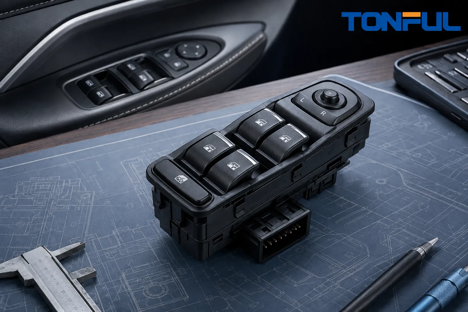
A power window switch may look like a simple set of buttons, but the wrong replacement can create fit, pinout, illumination, communication, or safety problems. Two switches can share the same outer shape while using different connectors, resistor values, automatic-window logic, lock functions, or vehicle coding. The correct buying decision therefore starts with controlled vehicle and electrical data—not a marketplace photograph.
This power window switch buying guide gives OEM buyers, aftermarket distributors, fleet suppliers, and quality teams an eight-check approval process. Use it to compare driver master switches, passenger switches, and electronic modules; verify an OE reference without relying on it alone; define validation evidence; and build an RFQ that suppliers can answer. Product drawings, vehicle service information, customer specifications, and approved samples always take precedence over general guidance.
Table of Contents
- 1. Verify the vehicle application and OE reference
- 2. Identify the switch architecture
- 3. Match the connector, pinout, and mounting
- 4. Confirm every function and human-interface detail
- 5. Evaluate electrical compatibility
- 6. Define the validation package
- 7. Audit supplier and production controls
- 8. Build the RFQ and approve the part
1. Verify the Vehicle Application and OE Reference
Record the vehicle make, model, model year, body style, destination market, trim, door position, steering configuration, and the vehicle identification details used by the customer. A model-year range may contain a mid-cycle harness or door-module change. Left-hand-drive and right-hand-drive vehicles can use different master-switch layouts, while visually similar trims may differ in window count, mirror controls, child locks, illumination, or one-touch functions.
Use the original part number and supersession history as a starting point, then verify the physical and electrical specification. A number molded into a housing may identify a subcomponent or tooling cavity rather than the complete service assembly. Record whether each reference is an OE service number, supplier number, customer stock code, engineering drawing number, or unverified cross-reference.
Tonful’s current automotive power window switch range presents vehicle brands and OE reference numbers that can help begin a sourcing enquiry. A catalog reference is not final fitment proof. The buyer should still confirm the connector, pinout, function matrix, door position, steering configuration, vehicle application, and approved sample before release.
For distribution programs, maintain three application statuses: confirmed fitment, VIN or configuration check required, and unverified reference. Avoid one broad “fits” claim covering vehicles that share a door-trim opening but not the same electrical architecture.
2. Identify the Power Window Switch Architecture

Conceptual illustration only—not an acceptance standard or laboratory record. Verify the architecture against the vehicle drawing and approved sample.
Driver Master Switch
A driver-door master assembly commonly controls several windows and may integrate window lock, door lock, mirror adjustment, illumination, and automatic-window functions. Count every rocker and secondary control, but also verify what each position commands. A four-rocker housing does not prove that all four channels use the same circuit design.
Passenger or Rear-Door Switch
A single-door switch may reverse motor polarity directly, send a resistance-coded request, or communicate with a door module. Confirm the door position because front and rear units can differ in bezel, connector keying, illumination, and lockout behavior. Do not assume that one passenger switch is universal across all doors.
Electronic or Networked Module
Some assemblies contain a PCB, microcontroller, resistors, LEDs, or a network interface instead of carrying full motor current through basic contacts. Replacement suitability then depends on hardware, communication, software or calibration, wake-up behavior, diagnostics, and vehicle configuration. Tonful’s automotive PCB connector guide explains relevant board-to-harness interfaces, but the vehicle schematic must define the actual switch architecture.
| Buying question | Mechanical/direct switch | Resistor-coded switch | Electronic/networked module |
|---|---|---|---|
| Main output | Contact path to a motor circuit or relay | Defined resistance values | Digital or conditioned signal |
| Critical match | Contact arrangement and load | Resistor ladder and tolerance | Protocol, hardware, software, and coding |
| Evidence | Pinout, continuity, and load test | Pinout and position-resistance chart | Interface specification and functional test |
| Substitution risk | Wrong terminal or current path | Incorrect command value | No communication or missing functions |
3. Match the Connector, Pinout, and Mounting
Compare mating connector faces in the same orientation. Record cavity count, populated terminals, terminal size, keying ribs, latch position, polarization, and any seal interface. Treat housing color as a secondary identifier only. A connector that physically mates can still have a different pin assignment, so never energize an unknown unit until its pinout and test method are approved.
Check housing length, width, depth, mounting clips, screws, locating tabs, bezel profile, rocker clearance, and installed orientation. Define datum locations and tolerances in the inspection drawing. The switch should seat without trimming the door panel, loading the connector, creating a rattle, or interfering with surrounding parts.
Terminal condition matters as much as housing fit. Inspect plating, contact alignment, terminal retention, cavity damage, seals, and evidence of fretting or overheating. Tonful’s automotive terminals and connectors page provides context for terminal and housing selection, but the approved mating interface remains the controlling requirement.
Housing material affects heat, impact, chemicals, appearance, and dimensional stability. The PA66 versus ABS automotive material comparison explains general tradeoffs. For a specific switch, require the approved resin grade, color, grain, UV exposure requirement, flammability requirement where applicable, and restricted-substance documentation rather than accepting a generic material family.
4. Confirm Every Function and Human-Interface Detail
Build a position-and-output matrix for every control. Include window up, window down, automatic up or down, neutral, window lock, door lock, unlock, mirror direction, mirror selection, and illumination where present. Record whether each action is momentary, maintained, two-stage, resistance-coded, or electronic. Where manual and one-touch operation share one rocker, verify the force-travel transition between stages.
For covered U.S. vehicle applications, FMVSS No. 118 addresses power-window operating conditions, automatic reversal, and actuation controls. The official NHTSA FMVSS 118 laboratory test procedure also documents the vehicle categories and test approach. Treat this as a vehicle-system requirement: it does not prove that a loose replacement switch or supplier sample is compliant by itself.
Assess symbol artwork, orientation, day and night visibility, backlight color, brightness, dimming behavior, and light leakage against an approved master. Do not approve color from an uncontrolled phone photograph. Define the light source, supply condition, viewing angle, measurement method, target, and acceptance sample when illumination is important.
Tactile quality should also be measurable. Specify actuation direction, force profile, travel, detent, return, free play, button alignment, sound, and consistency across positions. There is no defensible universal force or cycle-life value for every power window switch; the acceptance limits must come from the controlled drawing, customer specification, or qualification plan.
5. Evaluate Electrical Compatibility
Obtain the circuit diagram and terminal-function table. Identify supply, ground, illumination, motor or relay outputs, lockout circuits, resistance-coded lines, and communication pins. Confirm rated load and test load per circuit from the product specification. Do not infer current capability from terminal size or nominal vehicle voltage.
For a direct-contact switch, review voltage drop or contact resistance under the specified method, open-circuit isolation, bounce where relevant, dielectric requirements where applicable, and temperature rise under load. For resistance-coded controls, measure each commanded value and tolerance. A Stellantis master-window-switch service instruction illustrates why appearance alone is insufficient: the procedure checks physical operation and compares internal resistance readings with vehicle-specific service data. Those values apply only to that service case.
For an electronic module, add quiescent current, wake and sleep behavior, reverse-polarity and transient protection, communication, diagnostics, software identification, low-voltage behavior, and any programming or relearn requirement. Tonful’s automotive switch contact-resistance testing guide offers a measurement framework, but the power-window-switch specification must provide the method and limits.
6. Define the Validation Package

Conceptual illustration only—not an acceptance standard or traceable test report. Tests and limits must follow the approved specification and validation plan.
Use production-intent parts, connectors, harnesses, fixtures, software, and processes. The validation plan should identify sample quantity, conditioning, method, equipment range and accuracy, acceptance criteria, invalid-test and retest rules, responsibility, and report format. Select tests according to the switch architecture and vehicle environment instead of requesting a generic certificate bundle.
| Validation area | Evidence to request | Acceptance source |
|---|---|---|
| Dimensions and fit | Layout report, gauge result, and installed sample | Controlled drawing and vehicle interface |
| Pinout and functions | Position/output matrix for every control | Circuit diagram and functional specification |
| Electrical performance | Resistance or voltage-drop, isolation, and load results as applicable | Component technical specification |
| Tactile performance | Force-travel data, detent, return, and free-play results | Drawing or ergonomic specification |
| Durability | Cycle profile, electrical load, rate, environment, and interim checks | Qualification plan |
| Environmental resistance | Temperature, vibration, humidity, chemicals, dust, or ingress as specified | Customer or application requirement |
| Appearance and lighting | Color, texture, symbols, backlight, and leakage | Approved master and appearance standard |
Environmental exposure can change contact behavior, plastics, lubrication, seals, LEDs, and solder joints. Require initial and post-test functional and electrical measurements so that the report shows any change instead of merely recording chamber completion. If the switch operates inside a wet door environment, define protection at switch, connector, door, and harness level; do not transfer one component’s ingress rating to the complete door system.
Durability testing should use the intended electrical load, actuation sequence, rate, temperature, and intermediate inspections. Record the failure mode, not only the number of completed cycles. An unloaded test may not represent contact heating or arcing, while an unjustified accelerated rate may create unrealistic thermal conditions.
7. Audit Supplier and Production Controls
Trace requirements through Process Flow, PFMEA, Control Plan, Work Instruction, and Inspection Record. Critical characteristics may include mounting geometry, connector keying, pinout, resistor values, contact resistance, actuation force, illumination, markings, and software identification. Confirm first-piece checks after startup, tool change, material change, adjustment, and restart.
Review sub-supplier controls for contacts, terminals, springs, molded housings, PCBs, LEDs, coatings, lubricants, and printing. Check incoming identification, lot traceability, calibration, personnel authorization, nonconforming-product segregation, reaction plans, and change notification. Run a traceability exercise from one packaged sample back to material and process records, then forward to every related shipment.
Require notification before changes to resin, contact material or plating, spring, lubricant, PCB, electronic component, software, tooling, factory, sub-supplier, test method, artwork, or packaging. Supplier statements such as “OEM quality” should be converted into controlled characteristics, test records, and approved evidence.
8. Build the RFQ
Include these fields in the request for quotation:
- Vehicle, market, model year, trim, door position, and steering configuration
- OE and supplier references with source and supersession history
- Drawings, photographs, original or approved sample, and mounting details
- Connector interface, pinout, circuit diagram, and electrical architecture
- Rocker count, lock functions, automatic-window stages, mirror controls, and illumination
- Material, color, grain, symbols, tactile, sound, and appearance requirements
- Required validation methods, limits, sample quantities, reports, and approval authority
- Prototype quantity, annual forecast, order pattern, packaging, labeling, and logistics
- Tooling ownership, quality documents, traceability, warranty process, and change notification
Compare total program scope rather than unit price alone. Separate tooling, engineering, samples, validation, packaging, freight, and future change costs. Ask each supplier to mark every requirement as comply, clarification required, alternative proposed, or cannot comply, with an evidence reference and responsible owner.
Approve the switch only when vehicle fit, connector keying, pinout, functions, electrical architecture, tactile behavior, illumination, appearance, validation, traceability, and change control agree with the controlled requirement. Keep the approved sample and baseline data under revision control. Successful bench operation is useful evidence, but it does not replace vehicle-level functional and safety validation.
For a standard replacement or custom automotive-switch enquiry, send Tonful the application list, OE references, original sample or drawing, connector and pinout, function matrix, forecast, destination market, packaging needs, and required tests. Tonful can review the project scope and confirm applicable models, tooling, samples, documentation, MOQ, and lead time in writing before quotation.