
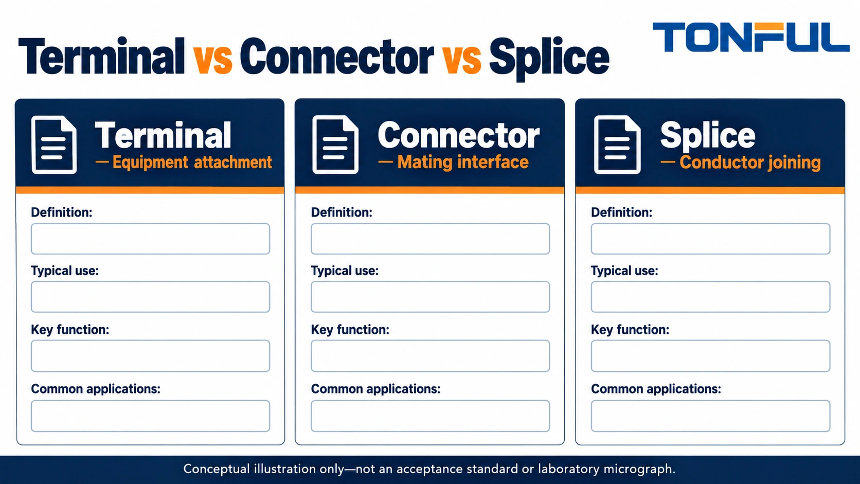
The useful distinction in terminal vs connector vs splice purchasing is the job the part performs. A terminal usually finishes a conductor for attachment to another connection point. A connector establishes an electrical interface and may contain terminals, housings and seals. A splice joins conductors into a continuous circuit, usually without a routine mating interface.
These names overlap in catalogs. A butt connector is commonly a splice; a connector housing may be sold without its terminals; a quick-disconnect terminal has a mating interface. Buyers should therefore describe the complete connection rather than approve a purchase from the product name alone. The following framework turns ambiguous terms into an auditable bill of materials.
Jump to: Definitions · Interfaces · Assembly · Protection · RFQ · Release
Terminal vs Connector vs Splice: Define the Purchased Item
Identify the smallest useful assembly
A ring terminal combines a conductor barrel with a closed attachment eye. It still needs an appropriate stud connection, hardware and enclosure. A ferrule gathers strands for insertion into a compatible terminal; it is not a complete terminal block. TONFUL’s cord end terminal page helps separate ferrules from other crimped ends when discussing a control-panel requirement.
A separable connector may need male and female contacts, housings, cavity plugs, wire seals, secondary locks and mounting features. Ordering the housing alone does not procure a usable connection. Some connector families are supplied assembled; others require several separately controlled part numbers.
A butt splice joins conductors through a metal body with conductor entry at each end. A branch splice joins a different circuit topology. Neither should be chosen simply because a supplier uses the broad word connector. Specify whether the purpose is extension, repair, reduction in conductor size or branching.
| Buyer term | Typical function | Items commonly missing from a vague RFQ |
|---|---|---|
| Terminal | Finish a conductor for an attachment point | Stud or tab dimensions, tooling, insulation support |
| Connector assembly | Join defined electrical interfaces | Mating half, contacts, seals, locks, cavity allocation |
| Splice | Join conductors along a circuit | Wire combination, body layout, sealing process |
| Terminal block | Provide an organized connection point | Mounting, end accessories, wire preparation instructions |
Separate function from process
Crimping, soldering, screw clamping and spring clamping describe how a conductor is terminated. Terminal, connector and splice describe a component or connection function. A connector may use crimped contacts, while a splice may use crimping or another permitted method. Asking whether to buy a crimp or a connector mixes two different decisions.
Use a short functional sentence on the requisition: connect this wire to this stud; connect this harness to this removable module; or permanently join these conductors inside this protected location. That sentence becomes the reference when two suppliers use different catalog terminology.
Start With the Interface and Service Task
Describe what the technician must disconnect
An equipment terminal suits a conductor that ends at a designated attachment point. A separable connector becomes useful when a module must be removed without disturbing individual conductors. A splice is appropriate when the circuit should remain continuous and service replacement can follow an approved cut-and-repair procedure.
Do not assume separability means unlimited mating cycles or disconnection under load. Those capabilities belong to the selected product specification and application. A convenient plug shape is not evidence of load-breaking capability, protection against accidental contact or suitability for a safety circuit.
Record access direction, available hand space, required tools and whether removal affects nearby circuits. A screw connection hidden behind a fitted panel may be inexpensive at assembly but difficult to service. Conversely, adding a connector to a circuit that never needs separation can add mating parts, inspection steps and identification requirements without a useful service benefit.
Distinguish installed and service envelopes
Measure more than the component body. Include wire exit direction, minimum permitted bend radius, latch travel, fastener access and the clearance needed to separate the interface. A right-angle part may solve an installed-height problem while creating a service-access problem.
Define the approved service action explicitly. Examples include disconnecting a module after isolation, replacing a complete harness or remaking a splice using a documented repair kit. These are planning scenarios, not claims that any unspecified terminal or connector is qualified for the task.

Compare the Assembly Process, Not Just the Piece Price
Count operations and purchased components
A ring-terminal connection may require one wire crimp plus equipment fastening. A typical two-ended butt splice requires preparation and termination at both ends. A crimp-contact connector requires wire preparation, contact termination, cavity loading and mating verification. Actual operation counts depend on the approved design; count them from the assembly drawing rather than assuming every family follows the same sequence.
For each option, list the number of metal bodies, conductor terminations, tooling setups, fastening steps and protection steps. Include sleeves or housings that are purchased separately. Distinguish the initial assembly cost from the cost of replacing a damaged interface during service.
| Process question | Terminal attachment | Separable connector | Conductor splice |
|---|---|---|---|
| Where is the conductor retained? | Terminal barrel or approved clamp | Contact termination inside assembly | Splice body or joining element |
| What completes the interface? | Stud, screw, tab or terminal entry | Specified mating parts | Approved conductor combination |
| What needs inspection? | Crimp and attachment | Terminations, loading, locking, mating | Each entry and protection system |
| What may require extra tooling? | Crimp and torque operation | Crimp, insertion or extraction | Crimp and sealing operations |
| How is repair controlled? | Replace damaged end and hardware as specified | Replace contact, housing or harness as permitted | Cut out and remake under repair instruction |
Keep tooling tied to the exact part
A general-purpose crimper listing does not establish compatibility with every terminal in its stated size range. Specify the tool, die or applicator and the wire-terminal combination. Include any locator, setup check and tool-maintenance requirements in the process plan.
Use TONFUL’s crimping-tool sourcing information to frame the inquiry, not to substitute a catalog range for an approved application. Ask whether the proposed tool recommendation includes the selected part number, conductor construction and expected inspection method.
Inventory complexity also matters. Two contacts that look alike can have different wire ranges or locking details. Label storage by part number and revision, and keep look-alike parts separated. A mixed bin can defeat an otherwise correct purchasing specification.
Specify Protection and Qualification at the Right Level
Insulation is not automatically sealing
An insulated barrel can reduce unintended contact at the terminated conductor, but it does not necessarily seal the wire entry or mating interface. A sealed assembly may need matched wire insulation diameter, correct cavity population and specific plugs for unused positions. Water resistance cannot be inferred from plastic color or a sleeve covering the metal.
TONFUL’s nylon-insulated terminal category is a product-family starting point. Compare the selected terminal’s dimensions and application documents before treating it as an alternative to a connector assembly. The polymer name alone does not establish environmental suitability.
Similarly, non-insulated terminals may suit installations where the surrounding design supplies the necessary protection. Their exposed metal must be addressed by enclosure, spacing and assembly requirements. Omitting factory insulation does not remove the need for an insulation strategy.
Ask which object the evidence covers
Distinguish a material declaration, component approval, supplier quality-system certificate and completed-assembly qualification. They answer different questions. A test report for one conductor size or one mating pair does not automatically cover an altered wire, seal or contact finish.
Record operating voltage, current duty, temperature exposure, vibration, contaminants and maintenance conditions as application inputs. Engineering must confirm suitability against the actual documents. Do not convert a wire gauge into a universal terminal current rating or assume a component rating is the rating of the entire harness.
Installation and service should be planned on isolated equipment. OSHA 1910.333 provides US electrical work-practice requirements for deenergization and related verification. This buying guide does not authorize live work, traction-battery repair, airbag-circuit modification or substitutions in safety-related systems.
Build an RFQ That Separates Parts From Evidence
Give suppliers a connection schedule
Use one row per connection, with a circuit identifier and the intended function. If two wires enter one termination, identify both separately and request explicit confirmation of the combination. Do not ask a supplier to infer a multi-wire approval from total nominal conductor area.
| RFQ field | Buyer entry | Supplier response requested |
|---|---|---|
| Connection function | Equipment end, separable interface or splice | Proposed family and complete part list |
| Conductors | Size, material, strand construction, insulation diameter | Supported combinations and documentation |
| Interface | Stud/thread, tab dimensions, mating family or topology | Drawing and dimensional match |
| Environment | Location, exposure and service conditions | Relevant specification scope and limitations |
| Production | Assembly method and available tooling | Compatible tooling and preparation instructions |
| Verification | Governing customer and engineering documents | Applicable reports and sample-review proposal |
| Supply controls | Packaging, identification and change notification | Traceability and substitution controls |
Request drawings before approving samples. A sample that physically fits may still have an unsuitable material, unsupported wire construction or missing locking feature. Keep dimensional approval separate from performance evidence and commercial approval.
Evaluate alternatives with the same boundary
When comparing quotations, normalize what is included. One price may cover only contacts, while another includes housings and seals. A splice quotation may omit the sealing sleeve or specified application tool. Document these exclusions rather than calling the cheaper line item equivalent.
Reject blanket equivalence statements without an identified mating or application basis. If the supplier proposes a replacement, require a difference list addressing dimensions, materials, tooling, conductor range, protection, service behavior and qualification scope. Unchanged appearance is not a controlled cross-reference.

Release the BOM With a Clear Substitution Rule
Close the purchasing loop
The released bill of materials should state exactly what arrives and how it is identified. Include separate part numbers for mating halves and accessories where applicable, approved wire combinations, controlled drawings and required assembly instructions. Specify who approves changes to material, geometry, plating, seals or tooling.
Before volume purchasing, review representative samples through the intended assembly route. Confirm fit, identification, accessibility and any verification required by the application plan. Record sample identity and disposition. A successful demonstration is useful development evidence, but it is not a substitute for the required qualification scope.
Send the completed connection schedule to TONFUL’s wire-terminal sourcing team for a part-level discussion. Ask for the proposed component list, drawings and tooling references rather than a broad promise of compatibility. Clear connection functions make quotations easier to compare and reduce the chance that a terminal, housing or splice accessory is missing when assembly starts.