
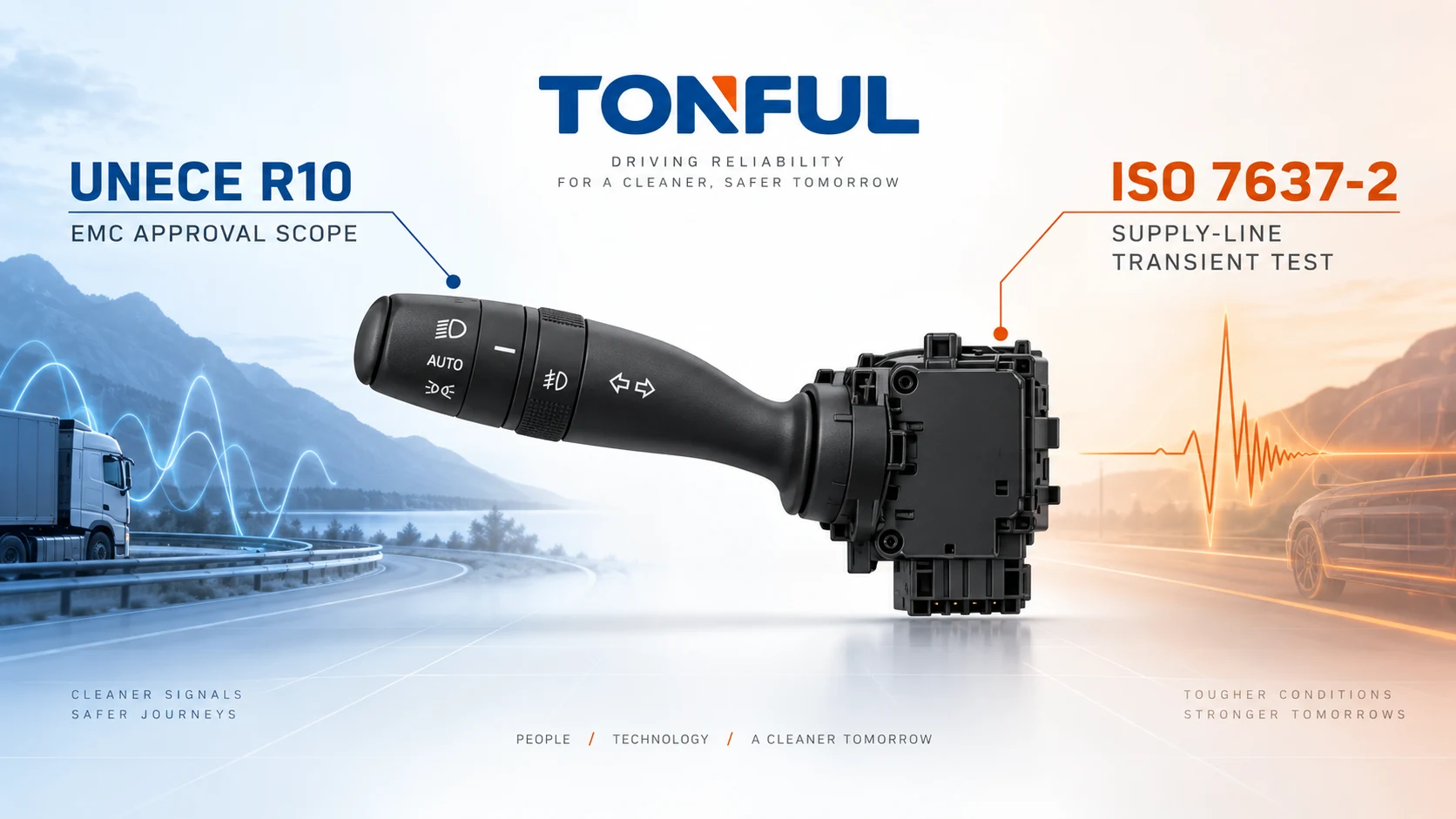
UNECE Regulation No. 10 and ISO 7637-2 are often placed in the same RFQ line, but they do not mean the same thing. UNECE R10 is a regulatory framework for electromagnetic compatibility of vehicles and electrical/electronic subassemblies in its approval scope. ISO 7637-2 defines bench methods for conducted electrical transients along supply lines of equipment installed in 12 V or 24 V road vehicles.
Whether either document matters to a stalk switch depends first on its architecture and market. A passive contact assembly may have no powered electronics, while an illuminated resistor-coded stalk, steering-column module or LIN/CAN device can contain circuitry susceptible to disturbances and capable of emissions. Buyers must define the actual product boundary instead of asking for a logo, certificate or generic “EMC test.”
On this page: Separate the Documents | Classify the Stalk | Build the Evidence Plan | Approve the Product
Separate the Documents
What UNECE R10 Addresses
The official UNECE collection for UN Regulation No. 10 identifies the regulation as electromagnetic compatibility and provides the revision and amendment documents. Its scope and approval route must be read in the edition applicable to the target market, vehicle category and product.
UNECE R10 can concern vehicle approval and, where applicable, approval of an electrical/electronic subassembly. The responsible party must determine whether the exact stalk assembly is in approval scope, whether it is covered as part of a larger steering-column module, and which series of amendments applies. A test report alone is not automatically a type approval. An approval mark or number must be checked against the approval document, product identity, manufacturer, extension history and technical-service evidence.
Do not describe a passive switch as “UNECE R10 certified” merely because it is installed in an approved vehicle. Conversely, do not assume an electronic stalk is exempt because its visible function is mechanical. Supply, illumination, sensing, communication and controller electronics can change the EMC boundary.
What ISO 7637-2 Addresses
ISO 7637-2:2011, confirmed current by ISO in 2025, specifies bench methods and procedures for conducted electrical transients along supply lines of equipment installed in passenger cars and commercial vehicles with 12 V or 24 V systems. The ISO summary also notes functional performance status classification.
It does not cover every EMC phenomenon, every signal line or every regulatory approval obligation. It does not by itself prove UNECE R10 approval. A project using ISO 7637-2 must still define applicable pulses, severity, source impedance, repetition, polarity, operating mode, harness/setup and functional status criteria from the controlled specification.
| Question | UNECE R10 | ISO 7637-2 |
|---|---|---|
| Nature | UN regulatory approval framework | International bench-test standard |
| Main concern | Vehicle/ESA electromagnetic compatibility in scope | Conducted transients on supply lines |
| Output | Approval evidence when applicable and granted | Test report and functional classification |
| Product boundary | Vehicle or defined electrical/electronic subassembly | Equipment under test and its supply interface |
| Does it prove the other? | No | No |
| Buyer action | Verify market, series, approval scope and identity | Define test plan, pulses, setup, states and criteria |

Treat regulatory approval, broader EMC validation and supply-line transient testing as related but separate evidence paths.
Classify the Stalk
Passive, Coded and Networked Designs
A contact-only stalk may switch a lamp, relay coil, wiper circuit or ground request. Its main risks can include contact voltage drop, arcing, thermal rise and unintended state during disturbances elsewhere in the system. If it has no powered electronics, some component-level immunity methods may not be technically meaningful on the switch alone; the applicable vehicle/OEM requirements still govern.
A resistance- or voltage-coded stalk uses a reference supply and maps positions to analog windows. Disturbances can shift decoded states, create false requests or stress protective components. Define reference supply, return, thresholds, filtering and receiving module because testing only the loose resistor network omits the actual interface.
A LIN/CAN stalk or steering-column module can emit and receive electromagnetic energy, reset, lose communication, store DTCs or command an unintended function. Define hardware, software, coding, wake/sleep behavior, bus termination and representative loads. The analog, resistive, LIN and CAN stalk guide helps classify the interface before selecting tests.
Illumination also matters. An LED and driver connected to the vehicle supply may create a different test boundary from a passive bulb feed. The LED versus incandescent load guide explains why load path and electronics must be confirmed rather than inferred from symbols.
Define the Tested Assembly
Record part number, revision, PCB and software, connector, mating harness, external controller, representative loads and support equipment. State whether the item is a stand-alone stalk, a combined clock-spring/module assembly or a subcomponent. Photograph connector orientation and identify every energized supply and ground.
Use the combination switch pinout guide to control cavity numbering. Applying a transient to a mirrored or misidentified pin can invalidate the test or damage a signal input.
Build the Evidence Plan
Translate the Requirement into a Matrix
| Record field | Required entry |
|---|---|
| Market/vehicle scope | Country, vehicle category and project |
| Product boundary | Passive stalk, coded switch, electronic module or assembly |
| Governing document | Regulation/standard/customer spec and exact revision |
| Approval requirement | Vehicle, ESA, covered assembly or not applicable with rationale |
| Supply domains | Nominal voltage, operating range and protected/unprotected feeds |
| Test methods | Emissions, immunity and transient methods actually required |
| Operating modes | OFF, active functions, wake, sleep and communication states |
| Monitoring | Inputs, outputs, current, bus, DTCs and unintended commands |
| Functional criteria | Status class and project-specific acceptance source |
| Configuration | Hardware, software, loads, harness, fixture and grounding |
| Report identity | Laboratory, equipment, calibration, raw files and date |
| Decision | Pass, fail, conditional or scope not tested |
For ISO 7637-2, identify the pulse and parameter source without reproducing proprietary standard tables in the article. Validate generator setup, coupling path and supply conditions. Monitor the switch continuously where a brief reset, false turn-signal request or missed wiper input would be hidden by a final-only check.
Acceptance must distinguish no degradation, temporary loss with self-recovery, reset/reinitialization, stored diagnostic event and permanent damage. Which status is allowed depends on the function and project. A temporary interruption may be unacceptable for one safety-related request even if another convenience function can recover.
Avoid Common Evidence Errors
- A supplier declaration is not the same as an approval certificate or complete report.
- One approved family member does not automatically cover another PCB, software or connector.
- A pass at one voltage architecture does not release the other.
- A laboratory accreditation scope does not prove the tested product passed.
- “Tested to ISO 7637-2” is incomplete without pulses, severities, setup and results.
- An E-mark image is not traceable without approval number and product-scope documents.
- Component immunity does not establish completed-vehicle compliance.
The 12 V versus 24 V combination switch guide provides additional supply-domain questions. Never scale a 12 V pulse plan to 24 V by simple arithmetic; use the controlled project requirement.
Control Samples, Setup and Changes
Use production-intent samples with unique IDs and genealogy. Define sample quantity, preconditioning, ambient conditions, fixture, harness length/routing, loads, support modules, communication traffic and monitoring bandwidth. Record generator and measurement equipment, calibration status and raw waveform references.
Retests need a preapproved rule. A proven setup failure may justify invalidation, but the original evidence must be retained. A product failure cannot be erased by testing a fresh sample without root-cause analysis.
After design release, assess changes to PCB, protection devices, oscillator, software, communication transceiver, illumination driver, grounding, connector, harness or housing. Determine whether the approval needs extension and whether regression testing is required.

Monitor supply, communication and every safety-relevant output during the disturbance rather than relying on a final function check.
Approve the Product
Review the Evidence Package
For UNECE R10, verify the applicable series, approval authority, approval number, manufacturer, trade name, type, variants, extensions and markings against the actual product. Confirm the document covers the supplied configuration, not merely a related module.
For ISO 7637-2, review the approved plan, sample list, circuit diagram, test setup, generator verification, operating modes, pulse records, functional monitoring, anomalies, DTCs, recovery and final inspection. A summary page without configuration and raw evidence is insufficient for engineering release.
When both requirements apply, maintain a claim-to-evidence matrix. The UNECE approval record supports only its regulatory scope. The ISO report supports only the tested transient scope. Other emissions, radiated immunity, signal-line coupling, ESD, environmental and endurance requirements need their own evidence.
Release Checklist
- The stalk architecture and every powered/interface circuit are classified.
- Target market and exact UNECE R10 series are identified.
- Approval applicability is documented by a competent responsible party.
- Approval identity and product configuration match.
- ISO 7637-2 pulse plan comes from a controlled requirement.
- Setup represents 12 V or 24 V supply, harness, loads and support modules.
- Operating modes and unintended outputs are monitored.
- Functional status criteria and DTC/recovery rules are approved before testing.
- Reports include sample, hardware, software, equipment and raw-data traceability.
- Design and process changes trigger regulatory and validation impact review.
Work With TONFUL
TONFUL’s automotive combination switch range provides current references for project discussion. Send the vehicle/market scope, complete OE identity, electrical architecture, 12 V/24 V domains, connector data, applicable regulatory requirement and customer test plan. TONFUL can compare candidate product evidence and samples with the defined requirement; no UNECE approval or ISO test status should be assumed without configuration-specific documents.