
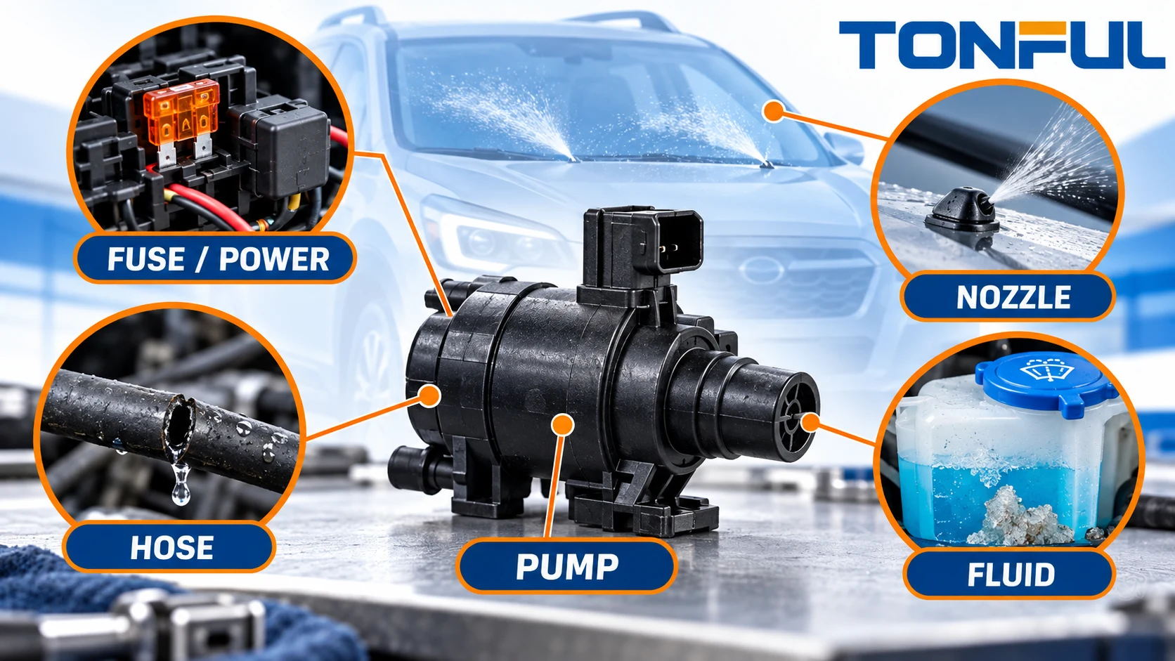
A windshield washer that does not spray is not automatically a failed pump. The same complaint can come from an empty reservoir, unsuitable or frozen fluid, a blown fuse, weak supply voltage, damaged wiring, a blocked pump inlet, a split hose, a faulty check valve or a clogged nozzle. Replacing the pump before separating these paths can add cost while leaving the original fault in place.
Diagnosis should follow the system from the driver request to the spray target. Observe the symptom, protect the vehicle, confirm fluid condition, inspect the hydraulic route and then test the electrical circuit under controlled conditions. This guide provides that routing logic without publishing a universal pinout, fuse value or pressure limit.
On this page: Symptom matrix | Safety | Diagnostic order | Evidence by fault | Repair verification | Diagnostic record
Washer Pump Failure Symptom Matrix
| Observable symptom | More likely investigation direction | First useful evidence |
|---|---|---|
| No pump sound and no spray | Fuse, command, supply, ground, connector or motor | Vehicle diagram and voltage/current under request |
| Pump sound but no spray | Empty fluid, inlet blockage, disconnected hose, frozen fluid or severe restriction | Reservoir level, inlet inspection and hose isolation |
| Weak or uneven spray | Low supply, pump wear, leak, restricted hose, valve or nozzle | Loaded voltage, current and staged hydraulic checks |
| Delayed spray after parking | Drain-back, air leak or check-valve behavior | Prime-retention observation and leak inspection |
| Fluid under reservoir | Grommet, pump inlet, reservoir crack or hose joint | Clean-and-dry leak trace |
| Front works but rear does not | Rear route, one reversible direction, valve, hose or nozzle | Polarity-to-outlet response and rear circuit isolation |
| Fuse opens again | Shorted wiring, seized pump, wrong fuse or overloaded circuit | Current test and harness inspection using vehicle procedure |
| Works intermittently | Loose terminal, module command, internal motor wear or moving-hose fault | Wiggle evidence, scan data and repeatable operating state |
This matrix routes the investigation; it does not prove a failed component. Record whether the reservoir was full, the ambient condition, which cleaning circuit was requested and whether the wipers or module responded. Those details prevent a technician from treating different symptoms as one generic “bad pump.”

Conceptual illustration only—not an acceptance standard or laboratory micrograph. Confirm every branch with the vehicle-specific service procedure.
Safety Boundary Before Testing
Park the vehicle securely, keep hands and tools clear of wiper movement, and follow the vehicle procedure before disconnecting components. Wipers can move unexpectedly when a washer request, automatic function or diagnostic command is active. Protect painted and electrical surfaces from spilled fluid.
Never apply power to an unidentified terminal. Do not use resistance or continuity mode on an energized circuit. A test lamp or direct jumper may overload a body-control or low-current driver circuit. When bench powering a confirmed pump, use the documented voltage, polarity, fused current-limited supply and suitable breakout leads. Avoid spreading female terminals with oversized probes or puncturing sealed wires unless the approved repair method permits it.
Do not repeatedly command a dry or blocked system. Toyota’s official owner information warns that continued operation with an empty washer tank can overheat the pump and advises checking nozzles when fluid is present but spray is absent. The guidance is vehicle-specific, but the diagnostic lesson is general: stop repeated operation and identify the missing fluid path.
A Repeatable Diagnostic Order
1. Confirm the Exact Complaint
Identify front, rear or headlamp washing; single or shared pump; one-time or intermittent behavior; and the environmental condition when the fault appeared. Verify that the customer is using the correct control. Some systems delay, pulse or route fluid differently from an older vehicle. A vehicle-specific Nissan bulletin, for example, explains that an unusual spray pattern can be normal for the listed models rather than a pump failure.
2. Check Fluid and Visible Condition
Confirm fluid level and the product used. Look for contamination, incorrect dilution, ice, gel, debris or mixed fluids. Inspect the reservoir, cap, pump seal and accessible hose joints. Do not substitute plain water where the vehicle or fluid manufacturer requires a formulated washer fluid.
3. Listen and Observe One Controlled Request
With safe access, command the affected circuit briefly. Record pump sound, wiper response, module messages, leakage and any fluid movement. A sound indicates motor movement but does not prove correct flow or pressure. Silence does not prove motor failure because the electrical request may not reach the pump.
4. Separate the Hydraulic Route
Inspect hose connections, kinks, pinches and moving-body transitions. If the approved procedure allows disconnection, isolate sections and capture fluid safely. Work from pump outlet toward the target so debris is not forced into a more sensitive component.
5. Test the Electrical Path
Use the wiring diagram to identify fuse, relay or module driver, connector cavities, supply and ground. Measure at the specified points during a command. A normal unloaded voltage can collapse when the pump draws current, so record voltage drop or loaded voltage as directed by the service information. TONFUL’s blade fuse product page supplies sourcing context, but the vehicle manual—not a generic blog—defines the correct circuit protection.
6. Confirm the Pump Separately
Only after terminal identity and test limits are known should the pump be evaluated on a protected bench fixture. Record supply at the pump, current, fluid, inlet arrangement, hose restriction and operating time. A pump that spins dry is not a meaningful hydraulic test and can be damaged.
7. Reassemble and Verify the Vehicle
The repair is not complete until the exact circuit sprays correctly, remains leak-free and preserves related functions. Clear or document diagnostic codes according to the vehicle procedure. Confirm front/rear direction when a reversible pump is used.
Evidence That Separates the Root Causes
Fuse, Command and Wiring Faults
A blown fuse is evidence of an overcurrent event, not permission to install a larger fuse. Inspect the pump connector for moisture, heat, backed-out terminals and damaged locks. Trace wiring at rub points and previous repairs. If a fuse opens again, stop and investigate current and short-circuit causes.
The command may originate in a stalk switch and pass through a module. TONFUL’s wiper switch diagnostic guide helps distinguish switch-side symptoms, while its auto combination switch range is relevant to sourcing. Neither establishes the washer-pump circuit for an unidentified vehicle.
Pump Inlet and Motor Faults
Debris at the reservoir pickup or pump screen can restrict flow while the motor remains functional. A PACCAR technical bulletin hosted by NHTSA instructs technicians for the specified application to confirm tubing restrictions and connections, then inspect the pump’s bottle-side mesh for debris before replacement. Apply that source only to its listed vehicle context; use it as evidence for inspection sequence, not a universal repair procedure.
Motor evidence includes no movement with confirmed supply and ground, abnormal current, intermittent operation, noise or inability to meet the controlled hydraulic requirement. State the acceptance source. Do not label a pump weak from sound alone.
Hose, Valve and Nozzle Faults
A disconnected or split hose may allow the pump to sound normal while fluid leaks inside the hood, body or liftgate. A kink can reduce flow without visible leakage. Check valves can stick, leak backward or add unintended restriction. Nozzles can be blocked, misaligned or damaged.
Do not push sharp objects into a nozzle unless the manufacturer procedure calls for it. Toyota’s owner guidance specifically warns against attempting to clear certain blocked nozzles with a pin because damage may result. If cleaning is allowed, use the approved method and verify spray afterward.
Fluid and Temperature Faults
Washer fluid must match the climate and materials. Frozen or partly frozen fluid can block hoses and strain the pump. Warm the vehicle safely and inspect for cracked components after thawing. Never use open flame or an uncontrolled heater. If contamination is found, preserve a sample when warranty or supplier analysis is required.

Conceptual illustration only—not an acceptance standard or laboratory micrograph. Test points and disassembly steps must follow controlled vehicle information.
Immediate Containment and Permanent Correction
If fluid is leaking near wiring or modules, stop operation, isolate the affected circuit under the service procedure and prevent further ingress. If the pump or connector is overheating, disconnect it only when safe and preserve the parts for analysis. When freezing or contamination affects a fleet batch, quarantine suspect fluid and inspect similarly exposed vehicles.
Permanent correction addresses the confirmed cause: repair the routed hose, replace the approved fuse after correcting the overcurrent, restore connector terminals, clean a permitted screen, use the specified fluid, replace a failed valve or install the correctly identified pump. TONFUL’s automotive electrical connector page and custom wire harness assembly page can support controlled replacement-component discussions when connector or harness damage is involved.
Avoid a repair that hides evidence. Repeatedly replacing fuses, swapping hoses at random or installing a higher-output pump can create a second fault and make root-cause confirmation harder.
Verify the Repair
Operate every affected function under the approved conditions. Confirm pump start, correct target, acceptable spray, no visible leak, stable electrical behavior and no new diagnostic messages. For a shared reversible pump, test both commands and verify that the inactive path does not discharge beyond the approved allowance.
Inspect the reservoir seal after the system has stood, then recheck flexible hose routes through their full movement. Record parts, lot or model identity, measurements, acceptance source and technician. If the pump was returned for supplier analysis, retain the original connector, seal and contamination evidence where possible.

Conceptual illustration only—not an acceptance standard or laboratory micrograph. Vehicle-level acceptance criteria remain project-specific.
Washer System Diagnostic Record
| Record field | Required entry |
|---|---|
| Vehicle and circuit | VIN/chassis where permitted, model, date and front/rear/headlamp path |
| Initial symptom | Sound, spray, leak, delay, intermittency and environmental condition |
| Fluid evidence | Level, type, temperature, contamination and freeze condition |
| Hydraulic evidence | Inlet, hose, valves, nozzles, restrictions and leak location |
| Electrical evidence | Diagram revision, fuse, command, voltage, ground, current and test points |
| Pump identity | Exact model, connector, outlets, revision and sample/lot if available |
| Root cause | Confirmed mechanism and evidence ID |
| Correction | Repair performed and replaced parts |
| Verification | All functions, leaks, codes and final result |
| Approval | Technician/reviewer and date |
Discuss Washer Pump Symptoms With TONFUL
For a replacement or supplier investigation, send TONFUL the vehicle and OE reference, removed-pump photographs, connector end view, inlet and outlet layout, nominal system voltage, symptom, diagnostic measurements and confirmed hydraulic condition. TONFUL can compare the request with its documented automotive washer pump range and discuss samples. Final release should remain tied to the exact vehicle circuit and verified root cause.