
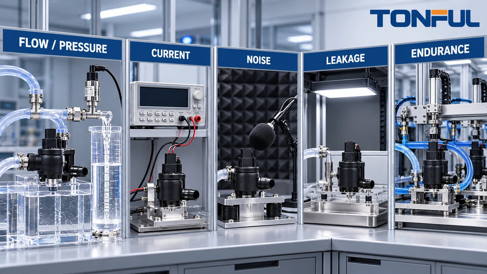
Washer pump testing should reproduce a defined electrical and hydraulic operating condition, not just prove that a motor spins. Flow changes with supply voltage, hose restriction, fluid viscosity and nozzle load. Current changes with motor condition and hydraulic demand. Noise depends on mounting, reservoir fill and the measurement environment. Endurance results are meaningful only when cycle definition, sample history and failure criteria are controlled.
A useful plan connects customer requirements to samples, fixtures, instruments, conditioning, measurements and a release decision. It also keeps development characterization, qualification, production audit and failure analysis separate. The following framework avoids unsupported universal limits while giving engineers and buyers a record they can apply to an exact product.
On this page: Test plan | Flow and pressure | Current | Noise | Environment | Endurance | Record
Define the Test Plan
Start with the pump model, revision, intended vehicle circuit, nominal system, control architecture and hydraulic path. Identify the document that supplies each acceptance criterion: customer drawing, product specification, vehicle requirement, qualification plan or approved engineering change. A test report should not create its own pass limit after results are known.
Sample Allocation
State sample quantity, lot selection and allocation before testing. Decide whether flow, electrical, environmental and endurance work uses independent samples or one sequentially aged group. Reserve an unaged reference sample when comparison is needed. Allocate destructive teardown samples separately, and identify any sample retained for supplier analysis.
Define invalid-test and replacement rules. A fixture leak, instrument failure or operator error may justify a documented repeat; a product failure does not. Record who approved sample quantity and the risk basis, such as development screening, customer qualification or production monitoring.
Fixture and Measurement Control
Record reservoir geometry, inlet seal, fluid, concentration, temperature, hose length and diameter, fittings, valves, nozzle or calibrated restriction, elevation and outlet destination. Measure voltage at the pump during operation. A bench supply setting is not the same as terminal voltage under load.
For every instrument, list model, range, resolution, accuracy and calibration status. Confirm that the sensor range covers startup and steady-state behavior without clipping. Establish data-acquisition rate and filtering where transients matter.

Conceptual illustration only—not an acceptance standard or laboratory micrograph. Every acceptance criterion requires a controlled source document.
TONFUL’s automotive washer pump category supports product discussions after these inputs are defined. Do not infer a model’s rating, qualification or vehicle coverage from the category page alone.
Flow and Pressure Testing
Establish an Operating Point
Flow and pressure are related through the system restriction. Free-flow volume can compare gross pumping ability, but it does not reproduce installed nozzles. Dead-head pressure can stress the pump and does not represent normal delivery. The approved plan should define the restriction or representative circuit and the duration of any maximum-pressure condition.
Condition fluid to the specified temperature and remove unintended air from the fixture. Verify reservoir level and inlet submergence. Record time from command to stable delivery, collected volume over a controlled interval, pressure location and any pulsation. Repeatability requires the same hose routing, valve orientation and nozzle condition.
For a reversible dual-outlet pump, test each direction separately. Identify polarity, Outlet A, Outlet B, active-path output and inactive-path leakage or cross-flow. If front and rear loads differ, use the respective fixtures rather than one generic restriction.
Leakage, Prime and Backflow
Inspect reservoir seal, pump housing, outlet joints and fixture connections before attributing fluid loss to the sample. Define leakage observation time and whether the pump is running or stopped. Prime retention and drain-back tests need a controlled stand time, hose elevation and fluid temperature.
Document check valves as part of the pump, nozzle or external circuit. A result without valve configuration cannot be compared fairly with another setup.
Electrical Current and Start Behavior
Measure current together with terminal voltage and hydraulic load. Capture startup peak only when the instrument bandwidth and sampling rate are suitable; otherwise label the result as a steady-state value. Record polarity, operating duration, fluid temperature and whether a relay, module or bench supply drives the pump.
Current by itself does not prove performance. Low current can indicate an open circuit or reduced mechanical load; high current can indicate restriction, drag, incorrect voltage or motor damage. Interpret it alongside flow, pressure, sound and temperature.
Use protected wiring and an approved fuse or current limit. Do not energize unidentified terminals or run the sample dry. For vehicle diagnosis, TONFUL’s blade fuse page and automotive connector page provide sourcing context, but the controlled circuit documentation governs protection and terminal access.
ISO 16750-2:2023 addresses electrical loads for road-vehicle electrical and electronic equipment in its applicable scope. It does not supply a universal washer-pump current limit, and it explicitly does not cover electromagnetic compatibility. If electronics, encoded control or a communication interface is present, define separate customer-approved EMC and ESD requirements.

Conceptual illustration only—not an acceptance standard or laboratory micrograph. Sensor positions, ranges and limits are project-specific.
Noise and Vibration
Noise must be measured in a controlled acoustic and mounting condition. A pump held in the hand, mounted rigidly to a metal bench or installed in a fluid reservoir can sound very different. Record fixture stiffness, grommet, reservoir fill, surrounding panels, microphone position, background level, operating voltage and hydraulic load.
Define whether the result is sound pressure, sound power, frequency content or a subjective abnormal-noise inspection. State weighting, time response, bandwidth, distance and room condition where applicable. Do not publish one decibel limit without the exact method and acceptance source.
Vibration evaluation should distinguish pump-generated vibration from vehicle environmental loading. An imbalance, loose internal component or cavitation can create a signature during operation. External vibration qualification asks whether the pump survives a controlled mechanical environment.
ISO 16750-3:2023 provides a road-vehicle mechanical-load framework where contractually applicable. Test severity, mounting orientation and pass criteria must still come from the customer or approved plan. Citing the standard does not prove TONFUL product compliance.
Environmental Conditioning
Temperature changes fluid viscosity, polymer behavior, seal compression and motor resistance. Define operating and storage conditions separately. Record whether performance measurements occur during conditioning, immediately after exposure or after recovery.
Humidity, water exposure, dust, salt or chemicals should reflect the mounting location and product construction. A submerged reservoir interface is different from an external connector exposure. Fluid-compatibility work should include the actual washer formulation, concentration and contamination risk.
ISO 16750-4:2023 addresses climatic loads within its scope. It does not automatically prescribe a complete washer-pump validation plan or universal severity. Select applicable tests through the product specification and installation environment.
After conditioning, repeat baseline measurements under the same controlled setup. Compare flow, pressure, current, leakage, noise and visual condition. Record both absolute results and change from initial values when the acceptance plan requires them.
Endurance Testing
Define One Cycle
Specify command duration, off time, voltage at the pump, hydraulic restriction, fluid temperature, reservoir level control and outlet selection. For reversible pumps, define the sequence and balance between directions. A “cycle” without this information cannot be compared across suppliers.
State total cycles or operating time only from the approved requirement. Define monitoring intervals and which measurements occur without interrupting the sequence. Automatic equipment should log supply, current, fixture pressure or flow state and any stop condition.
Control Sample History
Identify whether endurance follows environmental conditioning or uses fresh samples. Refill or circulate fluid without changing its controlled composition. Inspect filters and nozzles according to a predetermined schedule so maintenance does not hide product degradation.
If a sample fails, preserve the first-failure cycle, operating state, current waveform, fluid condition and fixture evidence. Do not restart and report only the final passing segment. Quarantine the sample for teardown when root-cause analysis is required.
Failure Criteria
Potential criteria include failure to start, loss of required flow or pressure, excessive current, leakage, unacceptable cross-flow, abnormal noise, housing damage, terminal overheating or failure of the installed function. Each needs a numerical or descriptive acceptance source. Avoid the vague statement “no abnormality” unless the inspection method defines what is observed.

Conceptual illustration only—not an acceptance standard or laboratory micrograph. Cycle definition and stop rules must be approved before execution.
Test Evidence Matrix
| Test area | Conditions to record | Result fields | Common evidence risk |
|---|---|---|---|
| Flow/pressure | Fluid, temperature, voltage, restriction, sensor location | Initial, aged, change, pass/fail | Free flow presented as installed performance |
| Current | Voltage, polarity, hydraulic load, sampling rate | Startup if valid, steady state, waveform | Comparing values under different restrictions |
| Leakage/backflow | Running/stopped state, time, elevation, valves | Location, amount/method, cross-flow | Fixture leak assigned to product |
| Noise | Mount, fill, load, microphone, room, weighting | Level/spectrum or defined observation | Hand-held test compared with installed result |
| Environment | Exposure, severity, orientation, recovery | Pre/post values and damage | Standard citation without project applicability |
| Endurance | Cycle, dwell, fluid, voltage, load, sample history | First failure, monitored trends, final result | Cycle count without cycle definition |
Qualification, Audit and Production Monitoring
Qualification demonstrates an approved design under a defined plan. A supplier audit reviews whether processes and records can sustain that design. Production monitoring checks selected characteristics for ongoing control. One activity does not replace the others.
An end-of-line functional test may confirm rotation, current window or basic flow but cannot reproduce every environmental and endurance condition. Define test coverage, limits, challenge-part checks and reaction plans. TONFUL’s custom wire harness page can support fixture-harness discussions, while its auto combination switch page provides command-component context; neither proves washer-pump qualification.
Copyable Washer Pump Test Record
| Record field | Required entry |
|---|---|
| Sample identity | Model, revision, lot, sample ID and prior history |
| Test purpose | Characterization, qualification, audit, production or failure analysis |
| Acceptance source | Drawing/specification/plan number and revision |
| Sample allocation | Quantity, test sequence, controls, teardown and replacement rule |
| Electrical setup | Voltage at pump, polarity, protection, wiring and command |
| Hydraulic setup | Reservoir, seal, fluid, temperature, hoses, valves, restriction and elevation |
| Instruments | Model, range, resolution, accuracy, calibration and sampling rate |
| Baseline results | Flow, pressure, current, leakage, prime, noise and visual condition |
| Conditioning/endurance | Exposure or cycle definition, monitoring and interruptions |
| Final results | Measured values, change from baseline and failure mode |
| Decision | Pass/fail, deviation, approver and date |
Discuss Washer Pump Validation With TONFUL
Send TONFUL the application, controlled drawing, electrical condition, hydraulic circuit, fluid, environmental requirements, sample quantity and acceptance-source documents. TONFUL can review the request against its documented washer-pump range and discuss samples or test evidence. Final approval must remain limited to the exact product and validated conditions.