
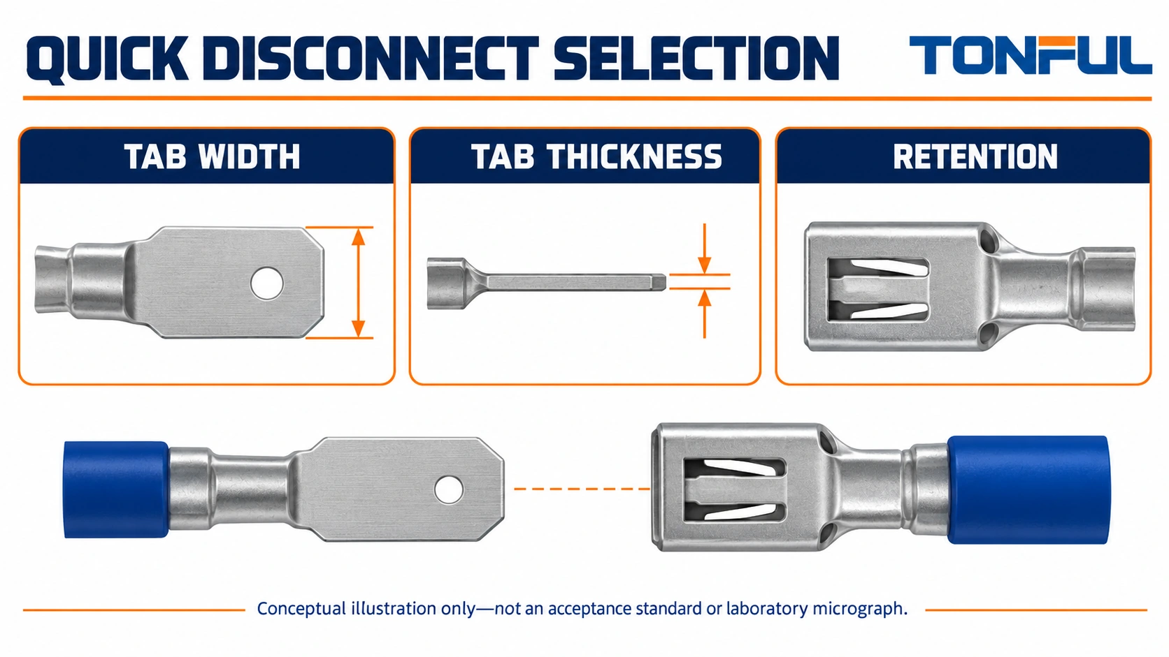
Quick disconnect terminal selection begins with a mating pair, not an isolated receptacle. The female terminal receives a male tab, while the wire barrel provides a separate crimped interface. A receptacle that looks the right width may still be incompatible with the tab thickness, lock arrangement or equipment envelope.
Use the actual tab and receptacle drawings to establish the interface, then match the conductor and tooling. Finally, review installation, retention and service access as part of the completed assembly. This guide provides a selection matrix and record structure without treating a nominal tab size, sleeve color or hand pull as proof of suitability.
Jump to: Mating pair | Dimensions | Retention | Wire and protection | Verification | Inquiry
Quick Disconnect Terminal Selection Starts With the Pair
Identify both sides of the connection
Record the equipment tab or male terminal part number alongside the female receptacle part number. If the tab is integral to a switch, motor or other component, obtain that component’s connection drawing. A photograph can help explain orientation, but it does not establish the dimensions or tolerances of the mating surface.
The TE Connectivity FASTON catalog is a useful primary-source example of a quick-connect product system that distinguishes tab dimensions, terminal styles and retention options. Use it to understand the kinds of interface information required, not to infer that a visually similar TONFUL candidate is interchangeable with a listed TE part.
Avoid terminology-driven purchasing errors
Quick disconnect can describe different terminal arrangements. This article addresses flat-tab electrical terminals and their receptacles, not fluid couplings, complete multipole connector housings or fork terminals under screws. The word spade is sometimes used for both blades and open forks, so attach a drawing when that term appears in an inquiry.
TONFUL’s male quick-disconnect explanation can help distinguish the tab side from the receiving side. Keep the two part identities separate in the bill of materials. A male terminal intended to crimp onto a wire is not necessarily the same interface as a tab formed directly on an equipment component.
Define the application conditions
List circuit function, operating conditions, access restrictions and expected service operations. Do not select the pair by current alone or derive current capability from tab width. Obtain the specific terminal and equipment information needed for the complete design, including the wire, surrounding thermal conditions and any required approval evidence.
Match Tab Width and Thickness
Treat width and thickness as independent inputs
Compare the tab’s specified width and thickness with the receptacle’s permitted mating dimensions, including tolerances. A width family is a shortlist criterion rather than a complete compatibility statement. If documentation identifies only width, ask for the missing thickness range before approving the pair. Do not assume the receptacle will compensate for any thickness that can be forced into it.
Use drawing dimensions and suitable inspection methods for incoming parts. Measurements from worn, bent or plated-over service samples may not represent the released geometry. Record the drawing revision and measurement location rather than copying an approximate dimension from a photograph or product listing.
| Selection input | Source document | Decision it supports |
|---|---|---|
| Tab width and tolerance | Equipment or male-terminal drawing | Receptacle family shortlist |
| Tab thickness and tolerance | Same controlled drawing | Approved mating-thickness range |
| Tab profile and entry features | Interface drawing | Correct entry and seating |
| Locking feature, if present | Matched interface instruction | Lock engagement and release |
| Receptacle envelope | Female-terminal drawing | Housing, barrier and cover clearance |
| Mating direction | Assembly drawing | Installation and service path |
Check features beyond a rectangular outline
Review the actual tab profile, lead-in and any specified detent or locking feature. A hole or indentation on a tab should not be assigned a retention function without the interface documentation. The receptacle construction must match the intended arrangement; similarity of the exterior sleeve does not establish the internal contact or lock geometry.
Do not squeeze an oversize receptacle with pliers or spread a tight one to make a pair fit. Those changes can alter the contact system without providing a controlled acceptance method. Contain suspect parts, verify the two identities and drawings, and obtain an approved replacement or engineering disposition.

Specify Retention and Release Behavior
Distinguish mating retention from wire retention
Mating retention concerns the tab and receptacle remaining connected. Crimp retention concerns the wire remaining in its barrel. These are different interfaces with different fixtures and acceptance sources. A successful wire pull test does not establish correct tab engagement, while a secure-feeling mating pair does not prove the wire crimp is acceptable.
Record whether the candidate relies on its specified contact geometry, includes a positive locking arrangement or needs an additional housing feature. Confirm how full seating is identified and how release is performed. Do not call every female disconnect a locking terminal simply because removal requires effort.
Include service access in the retention decision
If a release feature is present, verify that it remains accessible after the terminal is installed. A connection that can be released on the bench may be obstructed by the enclosure or adjacent wiring. Avoid routing the harness so that service personnel must pull the conductor to disconnect the pair. Follow the component’s specified handling and release method.
Clarify the required service-cycle conditions with the responsible designer. Repeated mating, unmating and exposure can be relevant to the application, but this guide does not assign a universal cycle life. Request product-specific data or a qualification plan where repeated service is an explicit requirement. Do not convert a convenient disconnect function into a claim of unlimited reuse.
Keep operating and maintenance claims separate
A separable terminal is not automatically a load-break device. Do not disconnect or reconnect it under load unless the equipment and interface are specifically designed and approved for that operation. Perform ordinary installation and servicing with safe isolation, control of stored energy and verification of the deenergized state by qualified personnel.
For restraint systems, traction circuits and other safety-critical equipment, follow the equipment maker’s approved service process and terminal system. Generic dimensions do not authorize substitution. If repair information is unavailable, stop rather than improvising a receptacle or bypassing a lock that appears inconvenient.
Check the Wire Barrel and Protection
Match the conductor independently
Record wire part number, conductor material, nominal area, strand construction and insulation diameter. The barrel must be suitable for that conductor, while any support feature must accommodate the jacket. Two receptacles with the same tab interface can have different wire ranges or barrel constructions. Keep both interface descriptions on the purchase specification.
Select the tool and cavity from the terminal application instruction. TONFUL’s crimping-tool information provides a starting point for a tooling discussion, but a generic size range does not qualify every receptacle. Specify the orientation, locator where required, strip instruction and completion method for the chosen part.
Describe which metal remains exposed
Review the nylon-insulated terminal category when a pre-insulated construction is relevant. Confirm whether the chosen sleeve covers only the barrel or also the mating region, and check compatibility with the tab’s surroundings. Fully insulated and partially insulated descriptions need a drawing to establish actual coverage.
TONFUL’s non-insulated terminal category supports the alternative where a separate housing or protection plan is intended. Bare construction does not establish a higher temperature capability, and a sleeve does not establish sealing. Obtain part-specific evidence for exposure, insulation requirements and any claimed approvals.
Review the installed envelope
Include the receptacle body, sleeve, wire exit, tab support and any release movement. Check clearance to barriers and covers with representative wire routing. The pair should seat without the harness pushing it sideways or holding it partly engaged. Do not use a sleeve’s external appearance as the only indicator of full seating.
Consider a hypothetical replacement receptacle that shares the old part’s nominal width but has a longer sleeve. Review whether the sleeve reaches a component shoulder before full seating, whether the wire exits toward a cover, and whether a release feature remains accessible. Even if the tab dimensions match, these envelope changes can hold the selection open. Record the interference and request another candidate; do not cut the sleeve or reshape the receptacle to bypass the problem.
Also keep material and plating requirements attached to the part identity. Matching dimensions alone does not establish an equivalent contact system or environmental capability. Request the proposed material specification and relevant application evidence rather than inferring them from a shiny surface or the sleeve color.
Build a Mating-Pair Verification Record
Keep fit evidence separate from qualification results
The following record is an editorial review template. Enter actual identities, drawing references and results; do not use it as a pre-completed pass sheet. It helps purchasing and engineering see whether a proposed alternative changes the tab interface, wire crimp or installed protection.
| Record field | Information required | Hold condition |
|---|---|---|
| Male identity | Equipment/tab part and drawing revision | Unknown or estimated interface |
| Female identity | Receptacle part and drawing revision | Uncontrolled substitute |
| Dimensional match | Width, thickness and feature compatibility | Only nominal width confirmed |
| Engagement | Seating and lock/release instruction | Release or seating method unclear |
| Wire crimp | Wire identity, tool, cavity and instruction | Wire or tooling not covered |
| Installed arrangement | Envelope, routing, guarding and service path | Interference or exposed-risk issue |
| Verification plan | Methods and acceptance-document references | Generic limits without a source |
| Approval | Responsible owner and released revision | Open deviation |

Verify the relevant interfaces under the plan
Where mating-force or retention testing is required, the qualification plan should define the fixture, force direction, conditioning, sample population and applicable acceptance source. Wire pull testing needs its own method and criteria. Do not compare mixed fixtures or treat an informal hand check as a numerical retention measurement.
Electrical or environmental qualification should use the actual mating pair, wire and installation conditions required by the application. A bench continuity check does not establish loaded temperature behavior or durability after service exposure. Keep any measured results traceable to the sample identities and approved method rather than presenting them as properties of every quick disconnect.
Send TONFUL a Complete Interface Request
Send the tab drawing, candidate receptacle description, wire specification and installed-space constraints to TONFUL. Include the required lock/release behavior, protection arrangement and service conditions. State which requirements come from the equipment instruction and which need supplier confirmation so the response can address the unresolved interfaces directly.
Ask TONFUL’s wire-terminal team for a candidate pair and the drawings and tooling information needed for review. Release production supply only after width, thickness, retention, wire fit and installed access are resolved together. A complete interface request is more useful than ordering by nominal tab width and discovering the missing requirements during assembly.