
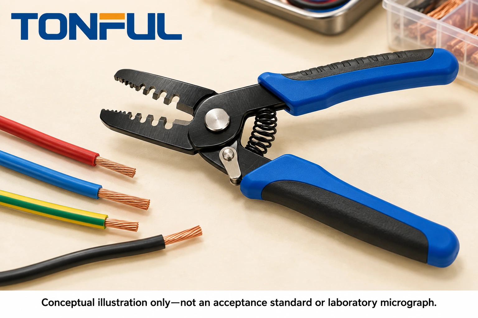
Wire strippers nick conductors when the cutting edges, wire position, or stripping motion let the tool contact metal instead of separating insulation cleanly. A wrong notch is one possibility, not a complete diagnosis. Blade damage, insulation variation, conductor construction, and off-axis pulling can produce similar-looking marks. Replacing the tool without preserving evidence may hide the actual cause.
For harness quality teams, the useful question is not simply whether a wire still conducts. It is whether preparation meets the applicable drawing and acceptance specification, and whether the process can repeat that result. This guide separates containment from confirmation and provides a record structure for deciding what to change before production resumes.
Contents:
- Establish the defect and safety boundary
- Diagnose five causes
- Verify the mechanism
- Use a traceable investigation record
- Prevent recurrence and define the tool request
Establish the Defect and Safety Boundary
Stop the affected operation and identify material produced since the last verified acceptable check. Preserve the suspect wire, removed insulation sleeves, tool identification, setting, operator, spool lot, and time window. Keep representative unprocessed wire from the same lot. Do not mix experimental strips with releasable production.
Work only on disconnected specimens or circuits isolated and verified safe through qualified site procedures. Ordinary grips are not evidence of live-work insulation. Keep fingers clear of jaws; isolate powered equipment according to its maintenance instructions before inspecting blades. Do not probe or adjust a moving mechanism to reproduce the fault.
A nick is localized removal or displacement of conductor metal. A superficial-looking line may instead be plating disturbance, a handling scratch, or lighting contrast. Photograph its position relative to the insulation shoulder and inspect the complete exposed circumference using the method required by your specification. Do not scrape away evidence to make the surface easier to see.
There is no universal allowable nick depth or missing-strand allowance supplied by this article. For a concrete product-specific example, TE Connectivity application specification 114-160996 directs preparation without nicking, scraping, or cutting the conductor. Its requirements apply to that connector system, not automatically to every harness. Obtain the actual customer document and revision before disposition.
Use TONFUL’s IPC/WHMA-A-620 revision and acceptance guide to organize the document discussion, not as a substitute for the controlled standard. A visible defect should remain on hold while engineering resolves an ambiguous criterion. Continuity alone cannot establish an undamaged cross-section or acceptable fatigue performance.

Why Wire Strippers Nick Conductors: Five Causes
1. Incorrect Notch or Excessive Blade Penetration
Symptom: a repeatable transverse mark appears near the insulation shoulder, sometimes with severed outer strands. Evidence: record the selected cavity, its solid/stranded marking, wire designation, actual construction, adjustment position, and removed sleeve. A nominal gauge label does not prove that every wire construction fits the opening.
Containment: hold affected ends and stop using the suspect setting. Rework only under an approved instruction, preserving required finished length. Confirmation: on sacrificial same-lot wire, compare the suspect setup with the documented correct cavity or depth, changing no other factor. Inspect specimens before terminal insertion. A disappearing mark supports the setting hypothesis but does not release earlier work.
Permanent action: establish the approved tool-and-wire pairing and adjustment procedure; replace an unsuitable tool rather than widening its notch by hand. Prevention: identify cavities clearly in the work instruction and require a first-piece check after wire-size or setting changes. Distinguish conductor area from insulation outside diameter in setup records.
2. Chipped, Burred, Worn, or Misaligned Blades
Symptom: an isolated gouge repeats at one side, removal force rises, or insulation tears rather than separating. Evidence: retain tool service history and photograph safely accessible cutting edges, debris, pivot play, and corresponding wire damage. Increased force is an observation, not proof that a blade is dull.
Containment: remove the suspect tool from service and identify output since the last satisfactory inspection. Confirmation: compare sacrificial strips using an inspected replacement tool of the same approved type. Correlate the repeated damage position with blade condition. If the problem persists, investigate material and positioning instead of declaring the replacement defective.
Permanent action: replace approved service parts or the complete tool according to manufacturer instructions. Do not grind an unknown edge profile into an apparently sharper shape. Prevention: add condition checks, approved cleaning, replacement-part control, and a reaction rule for rising stripping difficulty. A calendar replacement interval alone cannot detect accidental blade damage.
3. Off-Axis Positioning or Twisting During Removal
Symptom: damage favors one side, strip shoulders become angled, or results differ by operator. Evidence: observe the isolated task safely, recording wire support, insertion depth, pull direction, available clearance, and whether the operator rocks or rotates a tool not intended for that motion. Avoid assigning blame from one specimen.
Containment: pause the affected workstation and segregate its output. Confirmation: compare supported, aligned sacrificial specimens with the observed production method while retaining the same wire, tool, cavity, and setting. Repeat with trained operators under the approved trial plan. Consistent improvement supports an alignment mechanism, not a general conclusion about operator skill.
Permanent action: improve wire presentation, clearance, stops, and training for the actual tool motion. Prevention: show the permitted orientation in the work instruction and review workstation access whenever harness layout changes. Do not prescribe twisting as a universal stripping technique; some tooling requires a straight pull while specialized jacket tools work differently.
4. Insulation or Wire-Lot Variation
Symptom: a previously stable setup begins damaging one spool, color, or supplied construction. Evidence: compare supplier identity, lot, conductor strand arrangement, insulation material, outside diameter, wall consistency, and storage condition with retained reference wire. Do not infer conductor diameter from the outside of the insulation.
Containment: segregate the suspect lot and retain both stripped and unprocessed specimens. Confirmation: run a controlled comparison of reference and suspect material with the same inspected tool and documented setup. Use dimensional or section analysis only under an approved method. A lot-related change is not automatically supplier nonconformance; the material may conform but require a different qualified process.
Permanent action: resolve material conformance and approve a compatible setup or revised wire specification. Prevention: include relevant construction and insulation variables in purchasing and incoming-change controls. Require re-verification when the supplier changes material, strand design, or insulation system, even when the nominal conductor area remains unchanged.
5. Wrong Tool Principle or Uncontrolled Automatic Settings
Symptom: fine strands are shaved, thin insulation is inconsistently removed, or automatic gripping distorts the wire before stripping. Evidence: distinguish a jacket-removal tool from a conductor stripper and record gripper condition, blade selection, stop position, adjustment procedure, and approved wire range. Automatic action does not mean universal material recognition.
Containment: stop the incompatible combination and hold its output. Confirmation: test the intended conductor with a tool explicitly supported for that construction and insulation, following its manual. Change gripping and cutting settings separately where adjustment is permitted. If no documented combination exists, request supplier review rather than treating trial success as approval.
Permanent action: qualify a suitable tool or controlled recipe and document restrictions. Prevention: lock or identify approved settings where practical, control replacement blades, and require reapproval after recipe changes. TONFUL’s stripping tools model page separates wire strippers from jacket tools; use the selected model’s documentation rather than a family headline as the compatibility basis.
Verify the Mechanism Before Releasing Work
Begin with traceability and visual evidence, then dimensional checks that can distinguish the hypotheses. Examine wire construction and insulation eccentricity when relevant. Preserve a failed specimen before destructive testing; otherwise the very feature needed for root-cause confirmation may be lost.
Mechanical, electrical, cross-section, and environmental investigations are escalation options, not mandatory tests for every nick. Engineering should choose them according to defect risk and the governing qualification plan. A terminal pull test can fail because of stripping or crimping variables; passing it does not prove that a conductor surface complies with its preparation requirement.
Where resistance testing is justified, use isolated specimens and the approved four-wire method, defined current, Force/Sense positions, reference length, ambient condition, offset compensation, and reference-wire subtraction when applicable. Compare initial and conditioned results only under the same defined method. Never use a handheld continuity indication as a damage acceptance test or measure resistance on a live circuit.
Before testing, specify sample quantity and selection across the suspect window, equipment range and accuracy, fixture, conditioning, and acceptance-source revision. For mechanical tests, define pull speed and grip arrangement. Establish invalid-test and retest rules in advance; a fresh passing specimen must not erase a valid failure. Record observations separately from interpretation and identify any untested population remaining on hold.

Use a Traceable Investigation Record
The record should let another engineer reconstruct what changed and why release was authorized. The following fields are an editorial template, not a substitute for your quality procedure. Attach original images and raw measurements rather than only a conclusion such as “tool adjusted.”
| Record field | Required entry |
|---|---|
| Scope | Job, harness revision, wire supplier and lot, affected time window |
| Tooling | Tool ID, model, cavity, blade identity, setting, service status |
| Observation | Mark location, direction, affected strands, original photo ID |
| Trial | Hypothesis, changed factor, specimen IDs, method and sample plan |
| Criterion | Controlled document, revision, clause, responsible reviewer |
| Disposition | Hold, approved rework, scrap or authorized release; quantity |
| Closure | Corrective action, owner, due date, verification and restart record |
Keep stripping and termination evidence separate. TONFUL’s wire birdcaging discussion addresses a neighboring defect; spreading strands after insertion must not be silently relabeled as proof of blade contact. Inspect preparation before insertion whenever the investigation needs to distinguish the two stages.
Prevent Recurrence and Define the Tool Request
Transfer the confirmed mechanism into the control plan, not just a maintenance note. Define checks at setup, blade replacement, material change, and restart after interruption, with risk-based frequency during production. State who can adjust settings and who authorizes release. Recheck the corrected process under representative conditions before closing the action.
An acceptable restart sample is evidence for the corrected setup, not proof that all earlier output was sound. Review the suspect population separately and record how each quantity was dispositioned. If repeated stripping would shorten a lead below drawing requirements, replacing the lead may be necessary; do not conceal the damage inside a terminal or insulation sleeve.
When selecting replacements, start with the task separation in TONFUL’s electrical tools range. Request the selected model’s supported conductor construction, insulation compatibility, maintenance instructions, and spare-blade information. Cutting capacity and stripping capacity are different properties, even when both functions share one handle.
Send the wire specification, same-lot specimens, defect photos, tool identity, required strip length, and governing acceptance document through TONFUL product enquiries. Ask for a model-specific recommendation and a documented sample evaluation before ordering. That gives the supplier a reproducible problem to address without assuming that a catalog range, a successful crimp, or an undamaged-looking photograph proves process approval.